Download
1 / 18
180 likes | 184 Views
This document provides a detailed review of the commissioning process for the LHC Beam Interlock System, including the function, user systems, beam permit loops, and testing procedures.

E N D
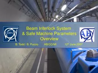
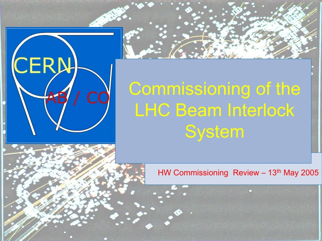
Commissioning of the LHC Beam Interlock System HW Commissioning Review – 13th May 2005
Function BIS & INJECTION ~120 User Systems distributed over 28kms Both-Beam LHC has 2 Beams Some User Systems give simultaneous permit Others give independent permit Beam-1 Beam-2 LHC Beam Interlock System
NOT Maskable Maskable User Systems Listing Work in Progress Total = 118 LHC Beam Interlock System
Beam Permit Loops & BICs Beam Dump Beam-1andBeam-2 16 Beam Interlock Controllers (BIC) Up to 20User Systems each 6 x Beam-1 8 x Both-Beam 6 x Beam-2 4 fibre-optic channels from Point 6 1 clockwise & 1 anticlockwise for each Beam • 10MHz Permit Loops generated at IP6 • Signal can be cutby any BIC • Signal can be monitoredby any BIC Missing 10Mhz triggers BEAM DUMP! Beam-1 / Beam-2 areindependent! LHC Beam Interlock System
Controller Block Diagram LHC Beam Interlock System
Controller Block Diagram LHC Beam Interlock System
Controller Block Diagram LHC Beam Interlock System
Test & Commission Full controller for any IR Left or Right Functionally Tested, Assembled and Power Soaked in the lab. Moved to the IR… connected together with installed cables. Then four steps of commissioning. 1. Stand Alone Testing (repeat of BIC lab test) 2. Beam Permit Loops Testing 3. Testing with User 4. Beam Dump Trigger Testing Testing Beam-1 is the same method as testing Beam-2 LHC Beam Interlock System
Basic Installation User System ‘A’ Permit ‘A’ Beam Interlock Controller Interface ‘B’ Permit ‘B’ User System Rack Beam Interlock System Rack VME Ethernet Redundancy ‘A’ and ‘B’ throughout Timing (UTC) Supervision LHC Beam Interlock System
1. Stand Alone Testing User System ‘A’ Permit ‘A’ Beam Interlock Controller Interface ‘B’ Permit ‘B’ User System Rack Beam Interlock System Rack Built in Test Function Tests Integrity of Interface to Controller Link ‘A’ inverse of ‘B’ during test LHC Beam Interlock System
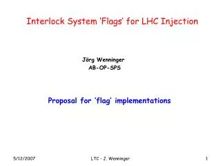
2. Beam Permit Loops Testing INITIALISE_LOOP BIC 4 BIC 6L Generator BIC 6R INITIALISE_LOOP = FALSE USER_PERMIT = FALSE ONE Loop Shown BIC 2 BIC 8 LHC Beam Interlock System
2. Beam Permit Loops Testing INITIALISE_LOOP BIC 4 BIC 6L Generator BIC 6R INITIALISE_LOOP = FALSE USER_PERMIT = TRUE BIC 2 BIC 8 LHC Beam Interlock System
2. Beam Permit Loops Testing INITIALISE_LOOP BIC 4 BIC 4 BIC 6L Generator BIC 6L BIC 6R BIC 6R INITIALISE_LOOP = TRUE USER_PERMIT = TRUE BIC 2 BIC 2 BIC 8 BIC 8 LHC Beam Interlock System
3. Testing with User User System ‘A’ Permit ‘A’ Beam Interlock Controller Interface ‘B’ Permit ‘B’ User System Rack Beam Interlock System Rack When User System Ready User must be able to deactivate ‘A’ / ‘B’ on request Fully verifies Critical Link to BIC… User System Interface Commissioned! LHC Beam Interlock System
3. Optional Verification User System Permit ‘A’ Beam Interlock Controller Interface Permit ‘B’ ‘A’ User System Rack ‘B’ Beam Interlock System Rack Tester Temporarily attach hardware Tester Tests from Input of Interface to Controller Standard Timer Circuit, ‘A’ inverse of ‘B’ during test LHC Beam Interlock System
4. Beam Dump Trigger Testing Communications between BIS and LBDS need to be checked… This can be done without User Systems, using the stand-alone Test Mode of the BIS Permit ‘A’ LHC Beam Dumping System Beam Interlock Controller Permit ‘B’ Checking ‘A’ AND ‘B’ will be part of the Cold Checkout… LHC Beam Interlock System
BIS Commissioning Summary • For the complete system.. Beam-1 AND Beam-2… How long? • Install and Test in Stand Alone…………………... ~2 days per BIC = 32 days • Test Connection from IR6 through rest of the machine………………. 2 days • Test User System Interconnection: ~2 hours per User => ~240 h ~= 30 days • Test Connection with the 2 Beam Dump Systems…………………….. 2 days Who? 2 to 3 person crew Performed parallel to other commissioning activities When? Phases #1 & #2 – End 2006 onwards Phase#3 – When User’s Come online Phase#4 – One of the final steps before LHC Startup Valuable BIS Commissioning Experience will be gained with SPS in 2006 – Time and Method LHC Beam Interlock System
FIN LHC Beam Interlock System