Download
1 / 16
160 likes | 316 Views
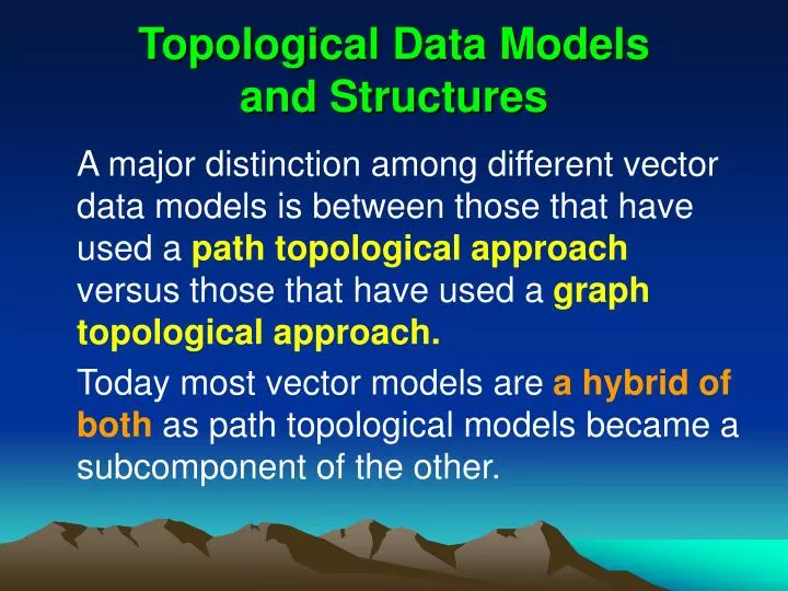
Topologi cal Data Models and Structures. A major distinction among different vector data models is between those that have used a path topological approach versus those that have used a graph topological approach.

E N D
Topological Data Models and Structures A major distinction among different vector data models is between those that have used a path topological approach versus those that have used a graph topological approach. Today most vector models are a hybrid of both as path topological models became a subcomponent of the other.
Path Topological Models (1) (x1,y1) (x2,y2) • Spaghetti Model (x12,y12) String Coordinate List (x13,y13) (x3,y3) (x11,y11) S1 (x1,y1), (x2,y2), (x3,y3), (x4,y4), P1 (x4,y4) (x5,y5), (x6,y6), (x7,y7), (x8,y8), (x10,y10) P2 (x9,y9), (x10,y10), (x11,y11), (x12,y12) (x5,y5) (x1,y1) (x9,y9) (x14,y14) (x6,y6) P3 (x3,y3), (x13,y13), (x14,y14) S2 (x7,y7) (x5,y5), (x14,y14), (x9,y9) (X8,y8) S3
Path Topological Models (2) (x1,y1) (x2,y2) • Polygon Model (x12,y12) Polygon Coordinate List (x13,y13) (x3,y3) (x11,y11) (x1,y1), (x2,y2), (x3,y3), (x13,y13), (x14, y14), (x9, y9), (x10,y10), (x11,y11), (x12,y12), (x1,y1) P1 P1 (x4,y4) (x10,y10) P2 (x5,y5) P2 (x3,y3), (x4,y4), (x5,y5), (x14,y14), (x13,y13), (x3,y3) (x9,y9) (x14,y14) (x6,y6) (x5,y5), (x6,y6), (x7,y7), (x8,y8), (x9,y9), (x14,y14), (x5,y5) P3 P3 (x7,y7) (X8,y8)
The Slivering Problem Polygon A Polygon B
Path Topological Models (3) (x1,y1) (x2,y2) Polygon Point List • Ppoint Dictionary Model (x12,y12) P1 p1, p2, p3, p13, p14, p9, p10, p11, p12, p1 (x13,y13) (x3,y3) (x11,y11) P2 p3, p4, p5, p14, p13, p3 P1 (x4,y4) (x10,y10) p5, p6, p7, p8, p9, p14, p5 P3 P2 (x5,y5) Point Coordinate (x9,y9) (x14,y14) (x6,y6) p1 (x1,y1) P3 (x7,y7) p2 (x2,y2) ... ... (X8,y8) p14 (x14,y14)
Path Topological Models (4) • CChain/Point Dictionary Model Polygon Chain List C1 C2 P1 C1, C2, C3 P2 C4, C5, C2 P1 C4 P2 P3 C6, C3, C5 C5 Chain Point List C3 p9, p10, p11, p12, p1, p2, p3 C1 P3 C2 p3, p13, p14 ··· ··· C6 p5, p6, p7, p8, p9 C6 Point file necessary
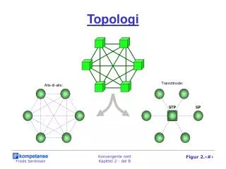
Graph Topological models • DIME (Dual Independent Map Encoding) File and a DIME segment Tract 101 p1 p2 Tract 102 From Endpoint p1 To Endpoint p2 Left Tract 101 Right Tract 102
DIME Model of a Map Line Segment From Point To Point Left Polygon Right Polygon L5 P4 L4 L6 L1 p9 p10 P4 P1 L3 L16 L2 p10 p11 P4 P1 L7 L2 P1 ··· ··· ··· ··· ··· P2 L7 p3 p4 P4 P2 L15 L8 L8 p4 p5 P4 P2 L1 L14 L9 p5 p6 P4 P3 L13 L9 L10 p6 p7 P4 P3 L10 L11 p9 p8 P3 P4 P3 L11 ··· ··· ··· ··· ··· L12 L16 p13 p3 P1 P2 Point file necessary
Retrieval from DIME Structure (1) Stage 1 – Retrieve all segments belonging to P3 L5 P4 L4 Seg. No. From To Left Right L6 L3 L9 p5 p6 P4 P3 L16 L10 p6 p7 P4 P3 L7 L2 P1 P2 L11 p9 p8 P3 P4 L15 L8 L1 L12 p8 p7 P3 P4 L14 L13 L9 L13 p9 p14 P1 P3 P3 L10 L14 p14 p5 P2 P3 L11 L12 Point file necessary
Retrieval from DIME Structure (2-3) Stage 2 – Reorder the segments for path topology L5 P4 L4 Seg. No. From To Left Right L6 L3 L9 p5 p6 P4 P3 L16 L10 p6 p7 P4 P3 L7 L2 P1 P2 L12 p7 p8 P4 P3 L15 L8 L1 L11 p8 p9 P4 P3 L14 L13 L9 L13 p9 p14 P1 P3 P3 L10 L14 p14 p5 P2 P3 L11 L12 Point file necessary
POLYVRT System Chain From Node To Node Left Polygon Right Polygon P4 C1 N2 C1 N1 N2 P4 P1 C2 C2 N2 N4 P2 P1 P1 C3 P2 C3 N2 N3 P4 P2 N3 C6 C4 N3 N1 P4 P3 C5 N1 C5 N1 N4 P1 P3 N4 P3 C6 N4 N3 P2 P3 C4 Point list for each chain necessary, a polygon file (circular list of chains) recorded
Node Model Cobounding Chains Right-hand Polygons Adjoining Nodes Node P4 C1 N1 C4 C5 C1 P4 P3 P1 N3 N4 N2 N2 N2 C2 C3 C1 P1 P2 P4 N4 N3 N1 C2 P1 C3 P2 N3 C6 C4 C3 P2 P3 P4 N4 N1 N2 C6 N3 N4 C6 C2 C5 P3 P2 P1 N3 N2 N1 C5 N1 N4 Polygon Node P3 P1 N1 P2 N2 C4 P3 N3 Chain file containing its list of points necessary
Four Corner Situation UT UT CO CO N N AZ NM N’ AZ NM
Extended Chain Model P4 From Node To Node Left Polygon Right Polygon Left Chain Right Chain C1 Chain N2 C1 N1 N2 P4 P1 C4 C2 C2 C2 N2 N4 P2 P1 C3 C5 P1 C3 P2 C3 N2 N3 P4 P2 C1 C6 C6 N3 C4 N3 N1 P4 P3 C3 C5 C5 N1 C5 N1 N4 P1 P3 C1 C6 N4 C6 N4 N3 P2 P3 C2 C4 P3 C4 A polygon file containing the ID of one chain on its boundary and a chain file containing its list of points are recorded
PAN Graphs P P A N A N ( a ) ( b )
Questions for Review • Please understand the spaghetti model, polygon model, point dictionary model and chain/point dictionary model of the data structures and their respective advantages and disadvantages. • Compare the DIME and POLYVRT file structures and their advantages and disadvantages. • Describe the process of the retrieval of the outlines of polygons using the node model and the extended chain model.