Download
1 / 17
170 likes | 183 Views
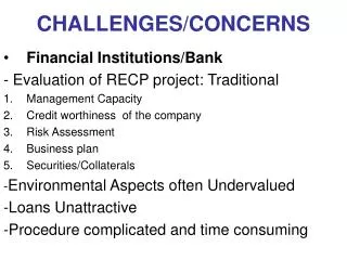
NSLS-II. Technical Challenges and Concerns S. Sharma and R. Alforque, R. Beuman, C. Foerster, E. Haas, E. Hu, P. Montanez, P. Mortazavi, S. Pjerov, J. Skaritka, C. Stelmach. Main Technical Concerns. Machine Specifications and Tolerances. Magnetic field quality Alignment of the SR magnets

E N D
NSLS-II Technical Challenges and Concerns S. Sharma and R. Alforque, R. Beuman, C. Foerster, E. Haas, E. Hu, P. Montanez, P. Mortazavi, S. Pjerov, J. Skaritka, C. Stelmach
Main Technical Concerns • Machine Specifications and Tolerances • Magnetic field quality • Alignment of the SR magnets • Vibration and thermal stability • Damping Wigglers • High power density beam with a large fan • Cryogenic Permanent Magnet Undulators (CPMUs) • Field measurement • Precise gap separation and thermal stability • Vacuum and impedance issues
Machine Specifications and Tolerances • Magnetic Field Quality Preliminary designs of the magnets are underway. Magnet vendors will be consulted about the final designs and tolerances. • SR sextupole alignment tolerance: 30 - 40 μm (2-σ cut) • BPM position stability (thermal):± 1 μm • Magnet position stability (thermal + vibration): 100 nm (rms, 4 – 50 Hz)
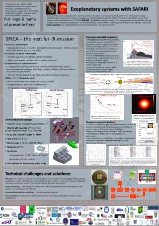
Australian Girder-Magnet Assembly SPring-8 Girder-Magnet Assembly Magnet Alignment • Very stiff girder with precisely machined slots for the magnet’s support frame. • Adjustable magnet support frame to precisely align magnetic axis to a fixed height. Magnets are directly bolted to the girder without shims or alignment hardware. • Six or more support points for the girder to minimize static deflection
Magnet Vibration due to Ambient Ground Motion • Ambient ground motion drops steeply as 1/ω4 • No significant vibration amplification for ω/ωn << 1 • First natural frequency of the girder-magnet assembly should be above 30 Hz.
Magnet Vibration • Low profile girder beam height of ~ 1m • No pedestals under the girder. • Several (6 or more) girder support points • Simple girder alignment mechanism • No alignment mechanisms between the girder and magnets. Support Concept APS Girder ALBA Girder-Magnet Assembly f1 = 57 Hz
NSLS-II SR and Booster Rings • Low profile booster and SR rings. The floor drops in the experimental hall by 0.4m to provide a beam height of 1.4 m. • Deep commercial anchors are cast in concrete eliminating the need for pedestals or grouting.
Sand Thermal Insulation Thermal Stability • Air and process water temperature regulation: ± 0.1 ºC • If necessary SR girders can be insulated and sand-filled. Thermally-Insulated NSRRC Girder
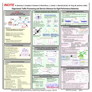
Dipole Chamber 7m Cooling Channel NSLS-II Damping Wigglers At 7m from the center of the wiggler, the fan is ~ 34 mm. Incidence power density at 0.6 mrad incidence = ~ 1.6 W/mm Aluminum chamber will require additional cooling channels.
Wiggler NSLS-II Damping Wigglers – Fixed Mask • Beam position interlock will be required to protect the chamber. • Incidence power density at 10 m and at 1.5 degree incidence = ~ 50 W/mm. A Glidcop fixed mask can handle this power density. • 10 GPM water flow ΔT ~ 30 ºC APS quad with exit port Gildcop Mask ~ 25 cm long
Thermal FatigueTests at APS (26-ID Beamline) • Realistic design criteria will be established based on thermal fatigue tests at APS. • Designs of high-heat-load absorbers and photon shutters will be optimized.
NSLS-II CPMU – Technical Challenges Magnetic Measurements of long small gap, UHV compatible undulators Precision control of the Undulator gap Effects of external environmental conditions on undulator gap control, energy and pointing stability. Temperature/Magnetic uniformity along magnet arrays Vacuum, Impedance, and beam dynamics issues associated with variable magnet gap to beam tube transitions and large chambers.
3-Meter In-vacuum CPMU based on X-25 Undulator Design NSLS X-25 Undulator Concept for NSLS-II We can extend experience gained from the Cryo-ready in-vacuum Undulator recently installed at X-25 to design the NSLSII CPMU’s. A long modern measurements bench and pulsed wire system in temperature-controlled clean room environment will be used for measurements and shimming.
Concept of an In-vacuum Cold Mapper for NSLSII CPMU’s In-vacuum Mapper with Hall probe in fully opened magnet gap Mapper mounted on custom flange cover.
Precision Gap Control in CPMU • Optical Micrometers will directly measure the Cold Magnet Gap to sub-micron accuracy • Measurement accuracy of ±1μm and resolution of ±0.1μm. • Studies are currently underway to study the effects of environmental factors. • Temperature feedback control may be implemented to the external Undulator structure
Undulator Impedance Issues • Detailed modeling of the X-25 and NSLS II undulator cavities will be performed. • If problems are observed during commissioning a feed back system will be implemented. • Undulator transition impedances will be studied and low impedance transition designs will be implemented
Summary There are concerns regarding machine tolerances, damping wigglers and CPMUs. The important technical issues are well known and are being addressed.