Download
1 / 44
440 likes | 446 Views
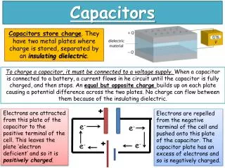
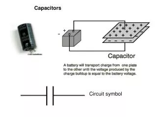
Capacitors. +. Dielectric. _. Capacitors. A capacitor is a device for storing electric charge. It can be any device which can store charges. Basically, capacitors consists of two metal plates separated by an insulator. The insulator is called dielectric . (e.g. polystyrene, oil or air)

E N D
+ Dielectric _ Capacitors • A capacitor is a device for storing electric charge. • It can be any device which can store charges. • Basically, capacitors consists of two metal plates separated by an insulator. The insulator is called dielectric. (e.g. polystyrene, oil or air) • Circuit symbol:
Examples of Capacitors • Paper, plastic, ceramic and mica capacitors • Electrolytic capacitors • Air capacitors
R R Charging a capacitor Q t Computer simulation 1
R R Charging a capacitor I I decreases exponentially with t. t
Charging and discharging capacitors • Video • Computer simulation 2
I Vc or Q t t Charging a Capacitor (2) • Current flow • Voltage-charge characteristics Vc ∝ Q
Charging of capacitors • When a capacitor is connected across a battery, electrons flow from the negative terminal of the battery to a plate of the capacitor connected to it. At the same rate, electrons flow from the other plate of the capacitor to the positive terminal of the battery. This gives a flow of current as the capacitor is being charged. • As charges accumulate on the plates of the capacitor, electric potential built across the plates. This hindersfurther accumulation of charges and makes the charge up current decreasing. When the potential difference across the plates equals that of the battery, the current becomes zero.
R R Discharging of Capacitors (1) Q t Computer simulation 1
R R Discharging of Capacitors (1) I t
t VC or Q I t Discharging a Capacitor (2) • Current flow • Voltage-charge characteristics
Capacitance (1) • Consider any isolated pair of conductors with charge Q Capacitance is defined as Unit : farad (F) where Q = charge on one conductor V= potential difference between two conductors
Capacitance of a Capacitor • Note that Q is not the net charge on the capacitor, which is zero. • Capacitance is a measure of a capacitor's ability to store charge. • The more charge a capacitor can hold at a given potential difference, the larger is the capacitance. • Capacitance is also a measure of the energy storage capability of a capacitor. • Unit of capacitance: CV-1 or farad (F). • Farad is a very large unit. Common units are 1mF = 10-6 F, 1nF = 10-9 F and 1pF = 10-12 F
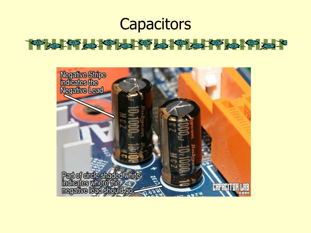
Markings of capacitor • Consider a ‘6.3V 1500mF’ capacitor shown in the following figure. Note that: • (1) Maximum voltage across the capacitor should not exceed 6.3 V, otherwise (leakage or) breakdown may occur. • (2) Capacitance of 1500mF means the capacitor holds 1500mC of charge for every 1 V of voltage across it.
Example 1 • Find the maximum charge stored by the capacitor shown in the figure above. • Solution:
Capacitance of an isolated conducting sphere • Capacitance = Q/V • For an isolated conducting sphere, Q + + + + + + + • ∴ C = Q/V = 4pea + - - - - - - - -
Example 2 • Find the capacitance of the earth given that the radius of the earth is 6 x 10⁶ m. • Solution
Note: • The earth’s capacitance is large compared with that of other conductors used in electrostatics. Consequently, when a charged conductor is ‘earthed’, it loses most of its charge to the earth or discharged.
area A +Q Electric field strength d –Q Parallel Plate Capacitor • Suppose two parallel plates of a capacitor each have a charge numerically equal to Q. • As C = Q/V • where Q = eEA and V= Ed C = eA/d • C depends on the geometry of the conductors.
Factors affecting capacitance of a parallel-plate capacitor • Geometrical properties of capacitor • Parallel plate capacitor capacitance depends on area and plate separation. For large C, we need area A large and separation d small.
Example 3 • The plates of parallel-plate capacitor in vacuum are 5 mm apart and 2 m2 in area. A potential difference of 10 kV is applied across the capacitor. Find (a) the capacitance • Solution
Example 3 • The plates of parallel-plate capacitor in vacuum are 5 mm apart and 2 m2 in area. A potential difference of 10 kV is applied across the capacitor. Find (b) the charge on each plate, and • Solution
Example 3 • The plates of parallel-plate capacitor in vacuum are 5 mm apart and 2 m2 in area. A potential difference of 10 kV is applied across the capacitor. Find (c) the magnitude of the electric field between the plates. • Solution
Application – variable capacitors • A variable capacitor is a capacitor whose capacitance may be intentionally and repeatedly changed mechanically or electronically • Variable capacitors are often used in circuits to tune a radio (therefore they are sometimes called tuning capacitors) • In mechanically controlled variable capacitors, the amount of plate surface area which overlaps can be changed as shown in the figure below. simulation
Permittivity of dielectric between the plates • A dielectric is an insulator under the influence of an E field. The following table shows some dielectrics and their corresponding relative permittivity. • Capacitance can be increased by replacing the dielectric with one of higher permittivity.
- - • - • - - • - - • - • - - net +ve charge net -ve charge + + Field Action of Dielectric (1) • A molecule can be regarded as a collection of atomic nuclei, positively charged, and surrounded by a cloud of negative electrons. no field no net charge • When the molecule is in an electric field, the nuclei are • urged in the direction of the field, and the electrons in • the opposite direction. • The molecule is said to be polarized.
Action of Dielectric (2) • When a dielectric is in a charged capacitor, charges appear as shown below. • These charges are of opposite sign to the charges on the plates. • The charges reduce the electric • field strength E between the plates. • The potential difference between • the plates is also reduced as E = V/d. • From C = Q/V, it follows that C is • increased.
Capacitors in series and parallel • Computer simulation 1 • Computer simulation 2
Formation of a Capacitor • Capacitors are formed all of the time in everyday situations: • when a charged thunderstorm cloud induces an opposite charge in the ground below, • when you put your hand near the monitor screen of this computer.
Charged Capacitor • A capacitor is said to be charged when there are more electrons on one conductor plate than on the other. When a capacitor is charged, energy is stored in the dielectric material in the form of an electrostatic field.
Functions of Dielectrics • It solves the mechanical problem of maintaining two large metal plates at a very small separation without actual contact. • Using a dielectric increases the maximum possible potential difference between the capacitor plates. • With the dielectric present, the p.d. for a given charge Q is reduced by a factor εr and hence the capacitance of the capacitor is increased.
Relative permittivity and Dielectric Strength • The ratio of the capacitance with and without the dielectric between the plates is called therelative permittivity. or dielectric constant. • The strength of a dielectric • is the potential gradient • (electric field strength) at • which its insulation breakdown.
+V -q +q +Q B A Capacitance of Metal Plates • Consider a metal plate A which has a charge +Q as shown. • If the plate is isolated, A will then have some potential V relative to earth and its capacitance C = Q/V. • Now suppose that another metal B is brought • near to A. • Induced charges –q and +q are then obtained • on B. This lowers the potential V to a value V’. • So C’ = Q/V’ > C.
Combination of Capacitor (1) • In series The resultant capacitance is smaller than the smallest Individual one.
Combination of Capacitors (2) • In parallel The resultant capacitance is greater Than the greatest individual one.
+ - V A V Measurement of Capacitance using Reed Switch • The capacitor is charged at a frequencyfto the p.d V across the supply, and each time discharged through the microammeter. During each time interval 1/f, a charge Q = CV is passed through the ammeter.
Stray Capacitance • The increased capacitance due to nearby objects is called the stray capacitance Cs which is defined by • C = Co + Cs • Where C is the measured capacitance. • Stray capacitance exists in all circuits to some extent. While usually to ground, it can occur between any two points with different potentials. • Sometimes stray capacitance can be used to advantage, usually you take it into account but often it's a monumental pain.
C Cs 1/d 0 Measurement of Stray Capacitance • In measuring capacitance of a capacitor, the stray capacitance can be found as follows:
Time Constant () • = CR • The time constant is used to measure how long it takes to charge a capacitor through a resistor. • The time constant may also be defined as the time taken for the charge to decay to 1/e times its initial value. • The greater the value of CR, the more slowly the charge is stored. • Half-life • The half-life is the time taken for the charge in a capacitor to decay to half of its initial value. • T1/2 = CR ln 2
Q 0 V Energy Stored in a Charged Capacitor • The area under the graph gives the energy stored in the capacitor.
Applications of Capacitors (1) • The capacitance is varied by • altering the overlap between • a fixed set of metal plates • and a moving set. These are • used to tune radio receiver. • Press the key on a computer keyboard reduce the capacitor spacing thus increasing the capacitance which can be detected electronically.
Applications of Capacitors (2) • Condenser microphone • sound pressure changes the spacing between a thin metallic membrane and the stationary back plate. The plates are charged to a total charge • A change in plate spacing will cause a change in charge Q and force a current through resistance R. This current "images" the sound pressure, making this a "pressure" microphone.
Applications of Capacitors (3) • Electronic flash on a camera • The battery charges up the flash’s capacitor over several seconds, and then the capacitor dumps the full charge into the flash tube almost instantly. • A high voltage pulse is generated across the flash tube. • The capacitor discharges through gas in the the flash tube and bright light is emitted.