Download
1 / 10
110 likes | 1.23k Views
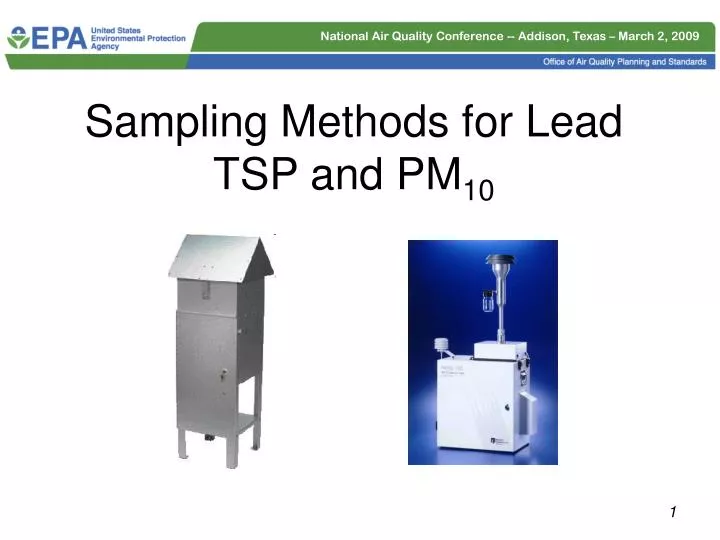
Sampling Methods for Lead TSP and PM 10. TSP. Sampling Technique for Pb-TSP. TSP is the indicator for Lead Includes ultra-coarse particles that might be missed by PM 10 sampling Sampling efficiency varies according to wind speed and direction Acceptable precision and bias

E N D
Sampling Technique for Pb-TSP • TSP is the indicator for Lead • Includes ultra-coarse particles that might be missed by PM10 sampling • Sampling efficiency varies according to wind speed and direction • Acceptable precision and bias • Sampler design already approved as FRM • Low volume alternatives have not been fully characterized • Most appropriate near sources and/or where emissions of ultra-coarse particles are expected
What sampler designs are approved for Pb-TSP sampling? • Any TSP sampler design that meets the requirements of Appendix B to Part 50, Reference Method for the Determination of Suspended Particulate Matter in the Atmosphere (High-Volume Method) is acceptable as for use as a FRM sampler for Pb-TSP. • Unlike other FRM samplers, EPA has not issued specific approvals for individual manufacturer versions of TSP samplers. Alternative types of flow control and measurement per sections 6.1 and 6.2 of Appendix B are acceptable. Any adaptations to the peaked roof design should be consistent with the requirements of sections 7.3.1 and 7.3.2 of Appendix B.
Performance Characteristics 7.3.1 The sampler shelter shall: a. Maintain the filter in a horizontal position at least 1 m above the sampler supporting surface so that sample air is drawn downward through the filter. b. Be rectangular in shape with a gabled roof, similar to the design shown in Figure 1. c. Cover and protect the filter and sampler from precipitation and other weather. d. Discharge exhaust air at least 40 cm from the sample air inlet. e. Be designed to minimize the collection of dust from the supporting surface by incorporating a baffle between the exhaust outlet and the supporting surface. 7.3.2 The sampler cover or roof shall overhang the sampler housing somewhat, as shown in Figure 1, and shall be mounted so as to form an air inlet gap between the cover and the sampler housing walls.†This sample air inlet should be approximately uniform on all sides of the sampler.†The area of the sample air inlet must be sized to provide an effective particle capture air velocity of between 20 and 35 cm/sec at the recommended operational flow rate. The capture velocity is the sample air flow rate divided by the inlet area measured in a horizontal plane at the lower edge of the cover.†Ideally, the inlet area and operational flow rate should be selected to obtain a capture air velocity of 25 ±2 cm/sec. Acceptable flow rate between 39 and 60 ft3/min – actual conditions
Re-conditioning Hi-vols for Use Flow Recorder • Check/replace gaskets • Replace motor brushes/use brush-less motors • Check tubing connecting flow measurement device • Calibrate/check entire system and adjust flow-controller for optimum range • Ensure flow standards are certified versus NIST standards • Purchasing new units is a desirable option as well – must meet App. B requirements Flow Controller Timer/Clock
Sampling Technique for Pb-PM10 • Use of Pb-PM10 can be approved by the Regional Administrator in certain situations, see 40 CFR Part 58 Appendix C. • High-volume PM10 samplers not approved for Pb-PM10 in support of NAAQS • Low-volume PM10 are approved for Pb-PM10 to meet NAAQS monitoring objectives. Advantages include: • Omni-directional inlet • Excellent precision and bias • Already approved as FRMs • Support sequential operation • Sample data can also support PM10 NAAQS (when calculated at STP) and PM10-2.5 (LTP)
What sampler designs are approved for Pb-PM10 sampling? • Low-volume PM10 samplers that meet the requirements for PM10C samplers (as described in Appendix O of Part 50) can be used for Pb-PM10 monitoring intended to meet NAAQS comparison objectives. • Good rule of thumb – if it’s an approved filter-based sampler for PM2.5 then you can use it for Pb-PM10 • just replace the PM2.5 separator with a straight-tube connector http://www.epa.gov/ttn/amtic/files/ambient/criteria/reference-equivalent-methods-list.pdf
Related Issues • Sampler spacing per 40 CFR Part 58 Appendix E • High-volume samplers (and other types of samplers drawing more than 200 liters/min of air) should be spaced a minimum of 2 meters away from other samplers and inlet probes. • Low-volume samplers should be placed a minimum of 1 meter away from other samplers and inlet probes. • Ensure that high volume sampler exhaust is ducted away from other samplers and probe inlets • Remember to leave room on sampling platform for QA samplers (collocated sampling and/or Pb-PEP)