Download
1 / 27
270 likes | 760 Views
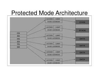
Interrupts in Protected-Mode. Writing a protected-mode interrupt-service routine for the timer-tick interrupt. Rationale. Usefulness of a general-purpose computer is dependent on its ability to interact with various peripheral devices attached to it (e.g., keyboard, display, disk-drives, etc.)

E N D
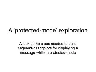
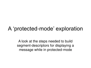
Interrupts in Protected-Mode Writing a protected-mode interrupt-service routine for the timer-tick interrupt
Rationale • Usefulness of a general-purpose computer is dependent on its ability to interact with various peripheral devices attached to it (e.g., keyboard, display, disk-drives, etc.) • Devices require a prompt response from the cpu when various events occur, even when the cpu is busy running a program • The x86 interrupt-mechanism provides this
Simplified Block Diagram Central Processing Unit Main Memory system bus I/O device I/O device I/O device I/O device
PM requirements • Unlike real-mode, where all code executes with full privileges (i.e., ring 0), protected-mode code usually is executed with some privilege restrictions (e.g., usually ring3) • Normally these restrictions prevent direct control of any of the peripheral devices • Thus, when responding to an interrupt in protected-mode, a ring-transition, and an accompanying stack-switch, are involved
IA-32 Interrupt-Gate Descriptors start-offset[ 31..16 ] P D P L 0 gate type Reserved (must be 0) code-segment selector start-offset[ 15..0 ] Legend: P=present (1=yes, 0=no) DPL=Descriptor Privilege-Level (0,1,2,3) code-selector (specifies memory-segment containing procedure code) start-offset (specifies the procedure’s entry-point within its code-segment) gate-types: 0x6 = 16bit Interrupt-Gate, 0x7 = 16-bit Trap-Gate 0xE = 32bit Interrupt-Gate, 0xF = 32-bit Trap-Gate
Trap-Gate vs. Interrupt-Gate • The only distinction between a Trap-Gate and an Interrupt-Gate is in whether or not the CPU will automatically clear the IF-bit (Interrupt-Flag in EFLAGS register) as part of its response to an interrupt-request • This is needed in cases where an Interrupt Service Routine executes outside ring0, so could not execute ‘cli’ or ‘sti’ instructions
16bit-Gate vs. 32bit-Gate • The CPU constructs different stackframes for the 16-bit versus the 32-bit gate-types 16-bits 32-bits ring0 stack ring0 stack SS SS SP ESP FLAGS EFLAGS CS CS IP EIP SS:SP SS:ESP = always pushed = pushed if privilege-level changed
Return-from-Interrupt • The programmer who writes an Interrupt Service Routine must know whether the Gate was 16-bit or 32-bit, in order to use the correct ‘interrupt-return’ instruction • In a code-segment whose default-bit is 0 (i.e., .code16), an ‘iret’ instruction performs the correct return-actions for a 16-bit Gate • Use ‘iretl’ for returning with a 32-bit Gate
Interrupt Descriptor Table • The Gate-Descriptors for device interrupts form an array (called the IDT) and reside in a special system memory-segment • The CPU will locate the IDT by referring to the value in its IDTR register (48-bits) • A pair of special instructions exists which allow reading and writing this register: sidt mem ; store IDTR into a memory-operand lidt mem ; load IDTR from a memory-operand
Format of register IDTR 47 16 15 0 base_address[ 31..0 ] segment-limit[ 15..0 ] 32-bits 16-bits The instruction ‘lidt’ is privileged (can only be executed in ring 0), but the instruction ‘sidt’ is unprivileged (it can execute in any ring) These features are analogous to the instructions ‘sgdt’ and ‘lgdt’ used to store or to load GDTR (Global Descriptor Table Register)
Register relationships code-segment Interrupt Descriptor Table (256 entries) ISR Interrupt-gate Global Descriptor Table code-descriptor INT ID GDTR IDTR
Two Interrupt-Controllers x86 CPU Serial-UART controller Master PIC (8259) Slave PIC (8259) INTR Keyboard controller Programmable Interval-Timer
Each PIC has a Mask Register IRQ 7 IRQ 6 IRQ 5 IRQ 4 IRQ 3 IRQ 2 IRQ 1 IRQ 0 Master PIC Interrupt-mask (I/O-port 0x21) IRQ 15 IRQ 14 IRQ 13 IRQ 12 IRQ 11 IRQ 10 IRQ 9 IRQ 8 Slave PIC Interrupt-mask (I/O-port 0xA1) If a mask-bit is 1, the corresponding device-interrupts are masked; If a mask-bit is 0, the corresponding device-interrupts are unmasked
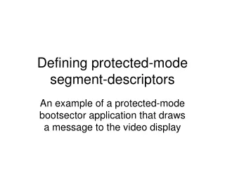
Demo-program: ‘tryisr32.s’ • Let’s create a ‘protected-mode’ program that will handle the timer-tick interrupts • Its ISR (Interrupt Service Routine) is very similar to the real-mode interrupt-handler • It increments a 32-bit counter (i.e., ‘jiffies’) • It sends EOI-notification to Master PIC • It must take care to preserve the values that are contained in the CPU’s registers
Two ‘threads’ in our demo program-variables (threads share access) ‘main’ program-thread Build descriptor-tables Enter protected-mode (most interrupts masked) Do for fifteen seconds: { Convert ‘jiffies’ value to hours, mins, secs Write time to screen } Leave protected-mode (most interrupts unmasked) Exit to our ‘loader’ jiffies Interrupt Service Routine Increment ‘jiffies’ value Issue an EOI command read write
Defining INT-8 Gate-Descriptor P=1 DPL=0 S=0 type=0xE 0x0000 isrTMR[31..16] 0x8E00 sel_CS isrTMR[15..0] 32-bit Interrupt-Gate selector for the ring0 code-segment Offset into code-segment of interrupt-handler’s entry-point
Some Key Steps in the Demo • Initialize the Descriptor-Table(s) • Enter Protected-Mode with IF=0 • Load GDTR, IDTR and segment-selectors • Mask all device-interrupts except timer • Set IF=1 to enable unmasked interrupts • Continuously show tick-count (for 15secs) • Reset IF=0 to disable interrupts (for exit)
‘identity-mapping’ • To make our demo as similar as possible to the code we would need in 64-bit mode (where ‘paging’ is always mandatory), we have chosen to enable paging in our demo and to use Intel’s 3-level mapping scheme (which supports 36-bit physical addresses) because it’s most like the 64-bit mode • However, we use an ‘identity-mapping’ of the bottom 1-megabyte (to keep it simple)
3-Level Translation Scheme PAGE FRAMES PAGE DIRECTORIES PAGE TABLES PAGE DIRECTORY POINTER TABLE CR3
3-level address-translation • The CPU examines any virtual address it encounters, subdividing it into four fields 31 30 29 21 20 12 11 0 index into page- directory pointer table index into page- directory index into page-table offset into page-frame 2-bits 9-bits 9-bits 12-bits Each ‘virtual address’ is 32-bits but gets mapped to a physical address which can contain 36-bits
The ‘pgdir’ and ‘pgtbl’ entries (Assumes PAE=1, but LME=0) 63 62 36 35 32 Reserved (must be 0) Page-frame physical base-address [35..32] 31 12 11 9 8 7 6 5 4 3 2 1 0 Page-frame physical base-address[31..12] avl A P C D P W T U W P Meaning of these bits varies with the table Legend: P = Present (1=yes, 0=no) PWT = Page Cache Disable (1=yes, 0=no) W = Writable (1=yes, 0=no) PWT = Page Write-Through (1=yes, 0=no) U = User-page (1=yes, 0=no) avl = available for user-defined purposes A = Accessed (1=yes, 0=no) EXB = Execution-disabled Bit (if EFER.NXE=1)
Page-directory-pointer entries (Assumes PAE=1, but LME=0) 63 62 36 35 32 Reserved (must be 0) Page-frame physical base-address [35..32] 31 12 11 9 8 7 6 5 4 3 2 1 0 Page-frame physical base-address[31..12] avl Reserved (must be 0) P C D P W T Rsv (0) P Legend: P = Present (1=yes, 0=no) PWT = Page Cache Disable (1=yes, 0=no) PWT = Page Write-Through (1=yes, 0=no) avl = available for user-defined purposes
What about IA-32e modes? • Some differences in what amount of CPU context information is saved on the stack • All stack-elements are quadwords (64-bits) • All the Interrupt Service Routines execute in 64-bit code-segments (i.e., ‘long mode’) • All memory-addresses involving registers CS, DS, ES, and SS are ‘flat’ addresses • All the IDT gate-descriptors are 128-bits
IA-32e IDT Gate descriptors 127 96 Reserved (must be 0) offset[63..32] offset[63..32] offset[31..16] Base[31..24] (if S=0) G D L A V L P D P L 0 X Gate Type C / D R / W Reserved (must be 0) IST code-segment selector offset[15..0] 31 0 P=Present Gate Type: 1110 = Interrupt-Gate, 1111 = Trap-Gate DPL = Descriptor Privilege Level IST = Interrupt Stack Table
64-bit interrupt-stackframe • The CPU constructs a different stackframe for the 64-bit IDT gate-types – its format is independent of any privilege-changes 64-bits ring0 stack SS RSP RFLAGS CS RIP SS:RSP = always pushed
In-class exercise #1 • Try modifying our ‘tryisr32.s’ program so that it does not use page-mapping at all (i.e., leave the PG-bit in CR0 turned off) • Do you discover any problems when you try to execute that modified program?
In-class Exercise #2 • Make a copy the ‘tryisr32.s’ file (named ‘tryisr64.s’) and see if you can discover what code-modifications are required if you wanted the timer’s ISR to execute from a 64-bit code-segment (rather than from the 32-bit code-segment it formerly used); try it out on an ‘anchor’ machine • (This exercise will help with Project #1)