Download
1 / 35
360 likes | 420 Views
ENGINEERING MECHANICS CHAPTER 2 FORCES & RESULTANTS. By Dr. P. Akila University college of Engineering villupuram. Slide 1 of 35. 2.1. Introduction. 1. Distinguish between vector and scalar quantities. 2. Determine the resultants of two force vectors by using

E N D
ENGINEERING MECHANICSCHAPTER 2FORCES & RESULTANTS By Dr. P. Akila University college of Engineering villupuram Slide 1 of 35
2.1 Introduction 1 Distinguish between vector and scalar quantities. 2 Determine the resultants of two force vectors by using vector triangle, parallelogram law and vector polygon addition. 3 Resolving a force vector into its components. 4 Determine the resultant of several force vectors using the method of perpendicular components. CHAPTER 2 - Forces & Resultants This chapter introduces the concept of vectors. Upon completion of this chapter, the student will be able Slide 2 of 35
5 cm 8 cm 9 cm 2.2 Vector Quantities Scalar quantity has only magnitude. Examples: 10 kg mass, 8 m long, 20 m2 area, etc. Vector quantity has magnitude + direction. E.g. 1) 5 km south. E.g. 2) 8 kN horizontal force. E.g. 3) 9 m/s north. Slide 3 of 35
1500 600 3 4 • Vectors may be in any direction: • Scalar quantities can be added algebraically: 3 cm + 5 cm = 8 cm 6 kg + 8 kg = 14 kg However, vector quantities cannot be added or subtracted because vector has the extra property of direction. Slide 4 of 35
y 8 kN 6 kN 0 60 0 40 x 2.3 Vector Triangle Method a) Graphical Method (Tip To Tail) • Choose a scale like 1 cm to 1 kN, then begin by drawing any force vector. 6 cm 400 x Slide 5 of 35
y 8 kN 6 kN 0 60 0 40 x 6 cm 400 x ii) Draw the other force taking care to join themtip-to-tail. 600 Tip of first arrow join to tail of next arrow. 8 cm Slide 6 of 35
y 8 kN 6 kN 0 60 0 40 600 x 8 cm 6 cm 400 x iii) Complete the triangle by drawing the resultant R from the start point of first arrow to end point of last arrow (force vector). End point R Startpoint Slide 7 of 35
y 8 kN 6 kN • 0 60 • 0 40 x 6 cm 6 cm 400 400 R 1500 8 cm 1500 8 cm 8 cm x x x Lets draw the diagram another way : start withthe 8 kN force instead Step 1 Step 2 Step 3 The same resultant R is obtained and it makes no difference which force you start to draw first, as long as you follow ‘Tip to Tail, join start point to end point’ rule. Slide 8 of 35
6 cm 400 x b) Analytical method Start by sketching the triangle ABC. A 8 cm Angle ABC = (300 + 400) = 700 600 R As triangle is not a right-angle, B Cosine Law is used here. C R = 8.20 kN Slide 9 of 35
8 kN 600 B 6 kN 400 x C 8.2 kN 73.50 To find direction of R, use sine rule to find ,then . 8.2 kN Slide 10 of 35
y 8 kN 6 kN • 0 60 • 0 40 x 2.4 Parallelogram Method a) Graphical Method • Use scale of 1 cm to 1 kN, draw the forces from the same point as in the diagram. Slide 11 of 35
y 8 kN 6 kN 0 60 0 40 x ii) Construct a parallelogram by drawing parallel lines as shown. 8 kN 600 6 kN 400 x Slide 12 of 35
y 8 kN 6 kN • 0 60 • 0 40 x R 8 kN 6 kN 400 x iii) Draw the diagonal R from the point where the tails of the two arrows meet. Note that half of the parallelogram is exactly the same triangle as that obtained by the Vector Triangle Method in 2.3. Slide 13 of 35
8 kN R 6 kN 400 x b) Analytical Method We can select any half of the parallelogram to solve for the resultant. The right half here is exactly the same as the one in 2.3 b) above and the analytical method use isalso exactly the same. Slide 14 of 35
4 kN 8 kN 3 kN 400 200 6 kN 2.5 Vector Polygon Method This method is used to find the resultant of three or more forces. Example below illustrates this principles Slide 15 of 35
4 kN 8 kN 3 kN 400 200 6 kN a) Graphical Method Start with any force drawn to scale, and follow tip-to-tail rule , draw the other 3 forces. 0 8 kN 40 end point R 4 kN start point 0 3 kN 20 6 kN Slide 16 of 35
1 3 2 4 kN 40 0 R R2 8 kN R1 20 0 6 kN 3 kN b) Analytical Method For 3 or more forces, this method involves more calculation steps. The polygon is divided into several triangles and cosine and sine rules are then applied. Using the example above: The polygon is divided into three triangles 1, 2 and 3 as shown. Starting with triangle 1, using cosine and sine rules, calculate R1. Then the process is repeated for triangle 2 to find R2, and finally triangle 3 to find R, the resultant of the four forces. This is very tedious and not the preferred method. * Check sections 2.6 and 2.7 for an easier method Slide 17 of 35
2.6 Resolution of A Force Into Components We know that resultant is the sum of 2 or more forces and it produces the same effect on a body. Hence a system of forces can be replaced by a single resultant force which have the same effect on the body. Conversely, a single force F (like a resultant), can be replaced by 2 forces or components of F, which produce the same effect on the body. Slide 18 of 35
The method of resolving a single force vector into two components is the reverse of vector addition. Any single force can be resolved into 2 components in any direction, but in order for us to develop an easier analytical method, we would choose to resolve a single force into its perpendicular components based on the x- and y-axis. Slide 19 of 35
y Fx = F cos F F y Fy = F sin x F x 2.7 Resolution of A Force Into Perpendicular Components One of the most important and useful concept is the resolution of a force vector into two perpendicular components, in the x and y axis as denoted by the Fx (x) andFy (y) components. Slide 20 of 35
300 Example 2.1 Resolve the 300 N force into components along the x and y axes. 300 N Sketch the parallelogram with Fy perpendicular to Fx. y 300 N Fy 300 x Fx Slide 21 of 35
Fy 300 x Fx Select any half of the triangle, a vector triangle, for analysis. As this is a right-angle triangle, cos 300 = Fx / 300 i.e Fx = 300 x cos 300 = 259.81 N Also since sin 300 = Fy / 300 i.e Fy = 300 sin 300 = 150 N Slide 22 of 35
y 8 kN 6 kN 0 60 0 40 x 2.8 Resolution of A Force By Fx And Fy Components For a number of forces, this section introduces an easier analytical method of finding the resultant. Students should master this method as it would form the basis of all your calculations for resultant forces. Let us use the same simple example in section 2.3 above to demonstrate the method: Slide 23 of 35
Fy= ( 4.0 kN) Fy= ( 3.86 kN) Fx= ( 4.6 kN) A Fx= ( 6.93 kN) • We first resolved the 2 forces into perpendicular i.e. Fx and Fy components. Fy= ( 8 x 10³ sin 30o) Fy= ( 6 x10³ sin 40o) 8 kN 6 kN 30 0 40 0 Fx= ( 6 x 10³ cos 40o) Fx= ( 8 x 10³ cos 30o) 2. The 2 forces can now be replaced by the above 4 components as shown below. Slide 24 of 35
Fy= ( 4.0 kN) Fy= ( 3.86 kN) Fx= ( 4.6 kN) A Fx= ( 6.93 kN) 3. Now we can add the two Fx forces to form a single Rx, as they are both horizontal forces but only opposite in direction, if we adopt a sign convention. Similarly, we can also add the two Fy forces to form a single Ry. Fx = Rx, isthe sum of all the Fx forces, Fy = Ry, isthe sum of all Fy forces. Fx = (4.6x10³) - (6.93x10³) {Fx pointing left is –ve} Rx = - 2.33 kN Fy= (3.86x10³) + (4.0x10³) {Fy pointing up is +ve} Ry = + 7.86 kN Slide 25 of 35
R Ry= 7.86 kN Rx= 2.33 kN 4. These two forces, Rx and Ry can now replace the previous four component forces in (2) above, and we can use the vector triangle method to add them back to form a single force, which is the resultant R, as shown by the vector triangle below. From the right-angle triangle, we then use the Pythagoras Theorem to find the magnitude of R. The angle of R is: • = tan -1 (Ry/Rx) = tan -1 ((7.86x10³)/(2.33x103)) • = 73.5 0 Same answers as before. The magnitude of R is: R = Rx2 + Ry2 = (2.33x10³)2 + (7.86x10³)2 = 8.2 kN Slide 26 of 35
Fy + ve Fx - ve Fx + ve -ve Fy 4. Direction of R: R R Ry Ry Rx Rx Rx Rx Ry Ry R R Resultant By Method of Perpendicular Components: Use the Sign convention for the force components: • Resolve all (but not horizontal or vertical) forces into Fx and Fy components. • Use Fx = Rx, Fy = Ry 3. Magnitude: R = Rx2 + Ry2 Angle: = tan -1 (Ry/Rx) (from x axis) Slide 27 of 35
0 80 N 20 150 N 0 30 x 0 15 100 N 110 N Example 2.2 Four forces act on a bolt as shown. Determine the resultant force. Solution: y Fx components in the x direction F1x = +150 cos 30 0 = 129.9 N F2x = +100 cos 15 0 = 96.6 N F3x = - 80 cos 70 0 = - 27.4 N F4x = 0 N, (for 110 N force) i.e. Fx = Rx = 150 cos 30 0 + 100 cos 15 0 - 80 cos 70 0 = 129.9 + 96.6 – 27.4 + 0 Rx = 199.1N Slide 28 of 35
y 0 80 N 20 150 N 0 30 x 0 15 100 N 110 N Fy components in the y direction F1y = +150 sin 30 0 = 75 N F2y = - 100 sin 15 0 = - 25.9 N F3y = + 80 sin 70 0 = 75.2 N F4y = - 110 N (it is a Fy or vertical force) i.e. Fy = Ry = 150 sin 30 0 - 100 sin 15 0 + 80 sin 70 0 = 75 – 25.9 +75.2 - 110 Ry = 14.3 N Slide 29 of 35
y 0 80 N 20 150 N 0 30 x 0 15 100 N 110 N R Rx Rx The magnitude of R is R = ( Rx2 + Ry2) R = ( 199.12 + 14.32) = 199.6 N The angle , R makes with the horizontal is = tan-1 Ry / Rx = tan-1 14.3 / 199.1 = 4.10 Since Rx and Ry are positive values, R = 199.6 N and = 4.10 Slide 30 of 35
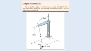
y 900,000 N 22250 N 22250 N 31 0 16 0 Example 2.3 The rocket’s main engine exerts a total thrust of 900,000 N parallel to the y axis. Each of its two small side engines exerts a thrust of 22,250 N in the direction as shown. Determine the magnitude and direction of the resultant force exerted on the rocket by the engines. Slide 31 of 35
Solution: Fx = Rx = 22,250 sin 16 – 22,250 sin 31 = - 5326.67 N Fy = Ry = -22,250 cos 16 – 22,250 cos 31 – 900,000 = - 21388 – 19072 – 900,000 = - 940460 N R = (Rx2 + Ry2) = (5326.672 + 9404602) = 940475 N tan = Ry / Rx = 940460 / 5326.67 = 176.55 = 89.68 0 R Slide 32 of 35
y 10 kN 0 P kN 60 a 8 kN x Special situations: 1. Resultant’s direction is along the x-axis (Horizontal) Fy = Ry = 0 Fx = Rx = R 2.Resultant’s direction is along the y-axis (Vertical) Fx = Rx = 0 Fy = Ry = R Example 2.4 A bracket is being pulled by 3 forces as shown. Determine the angle and the magnitude of force P if the resultant’s direction is along the y-axis and its magnitude is 20 kN. Slide 33 of 35
y 10 kN 0 P kN 60 a 8 kN x Since the resultant’s direction is along the y-axis. i.e Fx = Rx = 0 (No Rx component) and Fy = Ry = 20x103 N ( R must be = Ry) Fx = Rx = 0 (10x103)(cos 60o) + (8x10³) – (Px103)(cos ) = 0 (1) and Fy = Ry = 20x103 N (10x103)(sin 60o) + (Px103)(sin ) = 20 (2) Slide 34 of 35
y 10 kN 0 P kN 60 a 8 kN x From equation (1), P cos = 13 (3) From equation (2), P sin = 11.34 (4) Equation (4)/(3), P sin / P cos = (11.34 / 13) i.e. tan = 11.34 / 13 = 0.8723 = tan -1 (0.8723) = 41.1 0 To find magnitude of P, substitute = 41.1 0 into equations (1) or (2). P cos = 13 P = 13 / cos = 17.25 (P kN = 17.25 kN) End of Chapter 2 Slide 35 of 35