Download
1 / 32
360 likes | 649 Views
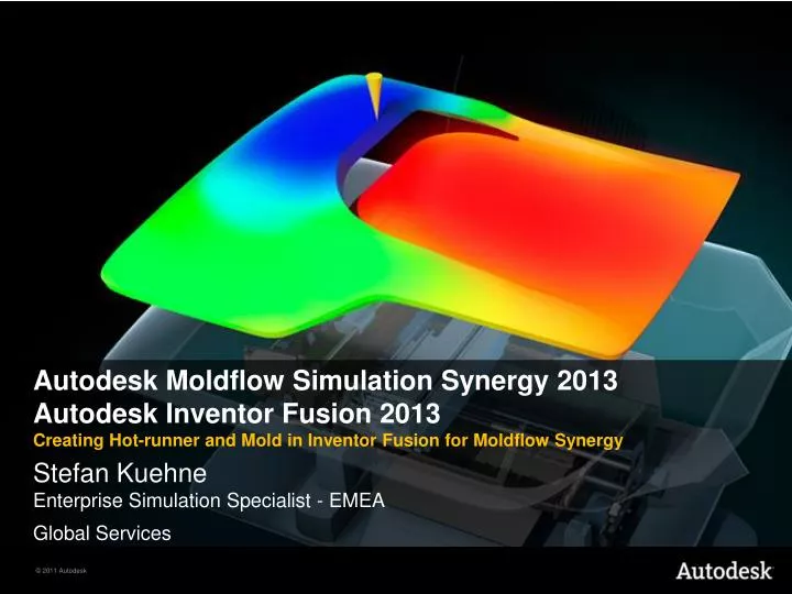
Autodesk Moldflow Simulation Synergy 2013 Autodesk Inventor Fusion 2013 C reating Hot-runner and Mold in Inventor Fusion for Moldflow Synergy. Stefan Kuehne Enterprise Simulation Specialist - EMEA Global Services. Hands On Overview. Guided. Given. Plastic part. Part 1:

E N D
Autodesk Moldflow Simulation Synergy 2013 Autodesk Inventor Fusion 2013 Creating Hot-runner and Mold in Inventor Fusion for Moldflow Synergy Stefan KuehneEnterprise Simulation Specialist - EMEA Global Services
Hands On Overview Guided Given Plastic part Part 1: Hot-runner creation Hot-runner Manifold Mold (cutting plane) Part 2: Mold creation
Inventor Fusion Hands On Hot-runner and Mold Open CAD Model in Inventor Fusion • Open the Hotrunner_PlasticPart.iam assembly file
Inventor Fusion Hands On Hot-runner and Mold Change color • To change the color for each part separate: • Select Part, right click and select “Material” • Click “Visual”, move the cross lines and the color-line • color-line Crosslines
3D Hot Runner & Mold creation out of nothing This video will show the steps for slide 7-12. Start the video first and then create the model. Follow slide 7-12.
Inventor Fusion Hands On Hot-runner and Mold First preparations • Change to Surface • De-select Plastic part
Inventor Fusion Hands On Hot-runner and Mold Close holes for the hot-runner • Patch edges • Select 1st. Edge • Click OK
Inventor Fusion Hands On Hot-runner and Mold Close holes for the hot-runner • Use the same procedure to close the other 4 edges
Inventor Fusion Hands On Hot-runner and Mold Create a new volume for the hot-runner melt • Select “Fluid Volume” • Select Internal • Select the model • Select 1st. Cap Surfaces
Inventor Fusion Hands On Hot-runner and Mold Create a new volume for the hot-runner melt • Select the other edges
Inventor Fusion Hands On Hot-runner and Mold Create a new volume for the hot-runner melt • Click OK A new volume as a solid body is created. It presence the hot melt and can be used in Insight as “Hot runner 3D”.
Inventor Fusion Hands On Hot-runner and Mold Mold creation • Select Solid in the Modelling tab • Select 2-Point Rectangle • Select the blue surface 1 2 3
Inventor Fusion Hands On Hot-runner and Mold Mold creation • Create a rectangle • Add dimensions 1000 220 300 500
Inventor Fusion Hands On Hot-runner and Mold Mold creation • Select “Extrude” • Select “New Component” • Select the hot-runner and the two circles • Use 500mm for the extrusion • Click OK
Inventor Fusion Hands On Hot-runner and Mold Mold creation • Select “Boolean” • “Cut”and “Keep Tools” • Target-> Mold
Inventor Fusion Hands On Hot-runner and Mold Mold creation • Select “Tools” • Select all 3 Components • Click OK
Inventor Fusion Hands On Hot-runner and Mold Coolant hole creation • Select Surface • Select “Center-Radius Circle”
Inventor Fusion Hands On Hot-runner and Mold Coolant hole creation • Add dimensions • Use 20mm for the circle • “Extrude” • Click OK • Click Done
Inventor Fusion Hands On Hot-runner and Mold Coolant hole creation • Select “Rectangular Pattern” • Select the Hole • Select “Direction” • Select 1st. Direction • Select 2nd. Direction • Use a 3 x 3 matrix
Inventor Fusion Hands On Hot-runner and Mold Coolant hole creation • Move the arrows
Inventor Fusion Hands On Hot-runner and Mold Coolant hole creation • Change View
Inventor Fusion Hands On Hot-runner and Mold Coolant hole creation • De-select two Coolant holes • Move the holes (to fit them) • Click OK
Inventor Fusion Hands On Hot-runner and Mold • Result: finished mold with holes for the cooling lines and voids for the runners and part.
Inventor Fusion Hands On Hot-runner and Mold Not guided: Create 3D lines in Inventor • Get only the mold into Inventor • Draw lines in the center of the coolant holes Tip: use 3D Sketch and Line Select the circle of the drilling and Inventor will find the center point
Inventor Fusion Hands On Hot-runner and Mold Not guided: Export to Moldflow Synergy • Inventor Fusion • Create a SAT file • The assembly including: • Plastic Part • Mold • Hot runner • Manifold • Inventor • Create an IGES file • Options: • Including • Coolinglines
Inventor Fusion Hands On Hot-runner and Mold Not guided: Export to Moldflow Synergy • Read into Synergy both files • The Synergy model include: • Plastic Part, • Hot-runner, • Manifold, • Mold, • Cooling Lines