Download
1 / 25
270 likes | 591 Views
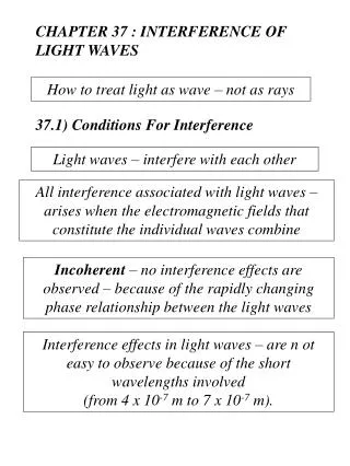
9.3 Interference of Waves in 2-Dimensions. Interference. When a wave crest meets a wave trough – destructive interference. Standing Waves. Recall – in a standing wave , points of continuous destructive interference are called NODES. Single Point Source. Point sources make circular waves.

E N D
Interference • When a wave crest meets a wave trough – destructive interference
Standing Waves • Recall – in a standing wave, points of continuous destructive interference are called NODES
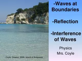
Single Point Source • Point sources make circular waves
Qualitative Analysis - 2 Point Interference • When a wave crest meets a trough, they cancel = destructive interference • No wave action
Two-Point Source Interference Pattern • Nodal lines numbered 1, 2, 3, …n • Equal distance between all nodal lines = Δx
Quantitative Analysis of 2 Point Interference • S1 and S2 are point sources • P1 is a point on nodal line # 1 • It was found by experiment that |P1S1 - P1S2|=1/2
And if we keep doing it we will find that Path difference is always 1/2 if the sources operate in phase. The general formula for path difference becomes: n = the nodal line number starting at 1
Derivation continued… • If we move Pn far away compared to the distance between the sources. • We end up with a right angle triangle • Therefore AS1 = d sin • sin = 1 give max # of nodal lines
Derivation continued… • Yet isn’t easy to measure… • ….Almost there…
Derivation continued… • xn = distance from right bisector (B to Pn) • L = distance from centre to node • Similar triangles • (ΔBPd similar to ΔAS1S2) • sin = xn/L
Derivation continued… Remember: xn is measured from the right bisector to the nodal line
Derivation continued… Δx=distance between nodal lines (m) L = perpendicular distance from slits to screen (m) d=distance between slits (m) λ=wavelength (m)
Maximum number of nodal lines Maximum value for sin = 1.0 d (1) = (n-1/2) λ)
Example 1 A 2 point sourcex (same frequency) generate a a point on the 2nd nodal line such that PS1 = 12.3 cm PS2 = 15.5 cm Determine the frequency and the λ of the waves.
Example 2 In a ripple tank the λ of the waves is 2.00 m. Two openings are 3.5 m apart. The end of the tank is 4.00 m beyond the openings. Where along the far wall of the tank is there little/no wave action?
Text Questions • Review example p. 473 into notes • 9.3 p. 459 #1-3 • 9.5 p. 473 #1-8 (2-pt interference) • 9.6 p. 478 #5,6