Download
1 / 26
270 likes | 393 Views
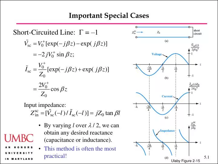
Important Special Cases. Short-Circuited Line: G = –1 Input impedance:. By varying l over l / 2, we can obtain any desired reactance (capacitance or inductance). This method is often the most practical! . Ulaby Figure 2-15. Important Special Cases.

E N D
Important Special Cases • Short-Circuited Line: G = –1 • Input impedance: • By varying l over l / 2, we can obtain any desired reactance (capacitance or inductance). • This method is often the most practical! Ulaby Figure 2-15
Important Special Cases Short-Circuited Line: Ulabyet al. Example 2-8 Question: Choose the length of a shorted 50 W lossless transmission line such that its input impedance at 2.25 GHz is equivalent to a capacitor with Ceq = 4 pF. The wave velocity is 0.75c. Answer: We have b = (2p f / 0.75 c) = (2p × 2.25×109 / 0.75 × 3.00×108 ) = 62.8 rads/m. We require tan bl = –1 / (Z0wCeq) = –1 / (50 × 2p × 2.25×109 × 4×10–12) = – 0.354. The arctangent yields bl = (2.80 + np) rads, (n = 0, 1, 2,…) = 2.80, 5.94, 9.08,… We conclude l = 4.5 cm, 9.4 cm, 14.5 cm… Ulabyet al. Figure 2-20
Important Special Cases • Open-Circuited Line: G = +1 • Using a network analyzer to measure and the formulae • we can determine Z0 and b for a transmission line from two measurements
Important Special Cases Quarter-Wave Transformer When allowing us to match a line with one impedance to a load with another. Ulabyet al. Example 2-10 Question: A Z01 = 50 W transmission line is to be matched to a resistive load with ZL = 100 W. What should be the characteristic impedance Z02 of a quarter-wave transformer? Answer: We want Zin = 50 W,to avoid reflections, entering thequarter-wave transformer, so that Ulaby Figure 2-22
Power Flow • Instantaneous Power • We find for the incident power on the load • Similarly for the reflected power,
Power Flow Average Power (Transferred to the Load) Of more importance is the power flow averaged over a period. — We calculate this value in both the time domain and the phasor domain Time Domain:
Power Flow Average Power (Transferred to the Load) Of more importance is the power flow averaged over a period. — We calculate this value in both the time domain and the phasor domain Phasor Domain: Our starting point is the key equation: This expression and similar equations appear in many contexts! — Substitution yields: which is the same as what was obtained before in the time domain
The Smith Chart • Points on the Complex G-Plane: • Examples: • GA = 0.3 + j0.4, • GB = –0.5 – j0.2 • NOTE: All points have • |G| 1 and lie on or withinthe unit circle Ulaby
The Smith Chart • Normalized Load Impedances: zL = ZL / Z0 • We have • Writing the normalized load impedance the sum of a normalized resistance • rL and a normalized reactance xL, so that zL = rL + jxL, we obtain • Keeping rL fixed and allowing xL to vary, we get circles on the G-plane • Keeping xL fixed and allowing rL to vary, we get circles on the G-plane
The Smith Chart Circles of constant rL andxL (1) Only rL 0 is allowed; any value of xL is possible (2) Circles of constant rL are contained within |G| = 1; rL = 0 corresponds to |G| = 1. (3) No circles of constant xL are contained within |G| = 1 (4) All circles touch G = 1 (5) Circles of constant rL and circles of constant xL intersect at 90o angles. Ulaby Figure 2-21
The Smith Chart Examples of use (1) Finding G: Given rL and xL,the x- and y-coordinates give Gi and Gr. The magnitude and phase give |G| and qr. (2) Finding Zin: Using the expression we conclude that zin is related to zL by a rotation by an angle –2b l on the Smith chart. (3) Finding SWR and voltage minima and maxima: On the circle of constant |G|, SWR = rL when Gi = 0, corresponding to Pmax. The angular rotation gives the minima and maxima, normalized to wavelength. The key point: The variation of the input impedance as a function of position in the transmission line can be tracedalong a circle on the Smith chart!
Applications—Paul High-Speed Digital Interconnects Consider a clock signal with rise and fall times tr and tf , a pulse durationt and a repetition period P = 1 / f0 . The spectrum will show harmonics at multiples of f0. We define: duty cycle = t / P50% duty cycles are typical We will consider a 1 MHz clock signal with 20 ns rise and fall times and a 50% duty cycle in the next figure Paul Figure 6.36
Applications—Paul High-Speed Digital Interconnects Three spectral components are visible (1) A falloff of 0 dB/decade up tof = 1/pt (2) Afalloff of 20 dB/decade up tof = 1/ptr (2) Afalloff of 40 dB/decade beyondf = 1/ptr Frequencies up to 3 /ptrare important. For example, that means that the spectrum of a signal with 1 ns rise and fall times is contained within 1 GHz. Paul Figure 6.37
Applications—Paul L L L High-Speed Digital Interconnects We model two gates connected through a land as a transmission line. These lands produce “ringing” in combination with high-frequency signal components Paul Figure 6.38
Applications—Paul L L Example: Two CMOS inverters with land interconnects SPICE model output • Inverter is modeled as a capacitor • Ringing is evident Paul Figure 6.40
Applications—Paul Example: Two CMOS inverters with land interconnects A matching scheme must be implemented to eliminate the ringing Paul Example on p. 319: * Ringing in Lands Between Two CMOS Gates VS 1 0 PWL(0 0 2N 2.5 20N 2.5 22N 0 40N 0) RS 1 2 25 T 2 0 3 0 Z0=53.4 TD=1.255N CL 3 0 5P LL 5 0 0.318U .TRAN 0.04N 40N 0 0.04N .PROBE .END SPICE model output Experimental output Paul Figure 6.41
Applications—Paul Crosstalk Between Transmission Lines There is a “hidden schematic” connecting two nearby transmission lines Paul Figure 6.49
Applications—Paul Crosstalk Between Transmission Lines Capacitive and Inductive coupling appear proportional to the time derivatives in the generator circuit Paul Figure 6.50
Applications—Paul Crosstalk Between Transmission Lines Experimentally observed near-end crosstalk Paul Figure 6.52
Applications—Paul Antenna Matching A quarter wave transformer is often used for this purpose Every antenna has an effectiveimpedance — often close to thevacuum impedance of 377 W. Quarter wave matching allows oneto match the antenna to a differentimpedance. However: one must carefully controlthe frequency and length! Paul Figure 6.48
Applications Using The Smith Chart • Impedance Matching Techniques • Quarter-wavelength transformer • Ulaby Module 2.7 • Discrete Element Matching: a capacitor or inductor can be inserted at an appropriate location along the transmission line to cancel match the line to the load • Ulaby Module 2.8 • Single-Stub Tuning: Instead of a lumped element, a shorted stub of appropriate length can be placed on the line to match the impedance. • Ulaby Module 2.9
Technology Brief 3: Microwave Ovens Invented by accident in 1940s at Ratheon by Percy Spencer while working on magnetrons for radar. When water molecules are subjected to an electric field, they rotate to orient their dipole with the field. Since the microwave field direction changes rapidly, the molecules vibrate, which causes the water to heat up. Penetration depth δp= 1/2αof microwaves into food depends on frequency, temperature, and water content.
Technology Brief 3: Microwave Ovens The magnetron, which generates the microwaves, needs 4 kV to operate. The oven is made of metal, which contains the microwaves. When the oven door is glass, there is a mesh to prevent the escape of the radiation. Microwaves cannot pass through the metal screen if the mesh width is much smaller than the wavelength of the microwave (λ ≈ 12 cm at 2.5 GHz). The stirrer mitigates the effect of the standing wave pattern created in the cavity, which would lead to unevenly cooked food.
Technology Brief 4: Cancer Zappers Microwave Ablation Microwave Ablation uses the same process as a microwave oven to destroy cancerous tissues. The ablation catheter (a transmission line) delivers 60 W of power at 915 MHz. The cancer cells are destroyed by overheating.
Technology Brief 4: Cancer Zappers High-Power Nanosecond Pulses Research shows that extremely short pulses of extremely high power radiation are effective in destroying malignant tumors. The pulses are about 200 ns long and have a peak power of 180 kW. The energy in each pulse is thus around 4 mJ. Even with the low energy, the high voltage is effective in destroying tumor cells.
Assignment • Reading:Ulaby, Chapter 3 • Problem Set 3:Some notes. • There are 7 problems. As always, YOU MUST SHOW YOUR WORK TO GET FULL CREDIT! • Please watch significant digits. • Get started early!