Download
1 / 62
620 likes | 625 Views
This course explores the fundamental concepts of modulation, coding, compression, and encryption techniques in mobile communications systems. Topics include analogue and digital modulation, error coding, and data compression.

E N D
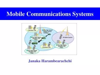
Mobile Communications SystemsECE IV Year I Sem Ms. Ayesha Fatima Assistant Professor ECE
Modulation, coding, compression and encryption techniques • 1 Analogue modulation: time domain (waveforms), frequency domain (spectra), amplitude modulation (am), frequency modulation (fm), phase modulation (pm) • 2 Digital modulation: waveforms and spectra, Frequency Shift Keying (FSK), Binary Phase Shift Keying (BPSK) [including Gaussian Minimum Shift Keying (GMSK)], Quadrature • Phase Shift Keying (QPSK) [including π/4QPSK] • 3 Error coding: General principles of block, convolutional, parity, interleaving • 4 Compression: Regular Pulse Excitation – Linear Predictive Coding – Long Term Prediction (RPE-LPC-LTP)
Overview Communication is the transfer of information from one place to another. This should be done - as efficiently as possible - with as much fidelity/reliability as possible - as securely as possible Communication System: Components/subsystems act together to accomplish information transfer/exchange.
Input message Output message Input Transducer Output Transducer Transmitter Channel Receiver Elements of a Communication System
Input Transducer: The message produced by a source must be convertedby a transducer to a form suitable for the particular type of communication system. Example: In electrical communications, speech waves are converted by a microphone to voltage variation. Transmitter: The transmitter processes the input signal to produce a signal suits to the characteristics of the transmission channel. Signal processing for transmission almost always involves modulation and may also include coding. In addition to modulation, other functions performed by the transmitter are amplification, filtering and coupling the modulated signal to the channel.
Channel: The channel can have different forms: The atmosphere (or free space), coaxial cable, fiber optic, waveguide, etc. The signal undergoes some amount of degradation from noise, interference and distortion Receiver: The receiver’s function is to extract the desired signal from the received signal at the channel output and to convert it to a form suitable for the output transducer. Other functions performed by the receiver: amplification (the received signal may be extremely weak), demodulation and filtering. Output Transducer: Converts the electric signal at its input into the form desired by the system user. Example: Loudspeaker, personal computer (PC), tape recorders.
To be transmitted, Information (Data) must be transformed to electromagnetic signals.
Electromagnetic Spectrum http://www.edumedia-sciences.com/a185_l2-transverse-electromagnetic-wave.html
Radio Wave Propagation Modes 1 Ground Wave Propagation Follows contour of the earth Can Propagate considerable distances Frequencies up to 2 MHz Example : AM radio
2 Sky Wave Propagation Signal reflected from ionized layer of atmosphere. Signal can travel a number of hops, back and forth Examples SW radio 3 Line-of-Sight Propagation Transmitting and receiving antennas must be within line of sight example Satellite communication Ground communication
ANALOG AND DIGITAL Data (Information) can be analog or digital. The term analog data refers to information that is continuous; digital data refers to information that has discrete states. Analog data take on continuous values. Digital data take on discrete values. Topics discussed in this section: Analog and Digital DataAnalog and Digital SignalsPeriodic and Nonperiodic Signals
Data can be analog or digital. Analog data are continuous and take continuous values. Digital data have discrete states and take discrete values.
Signals can be analog or digital. Analog signals can have an infinite number of values in a range; digital signals can have only a limited number of values.
In communication systems, we commonly use periodic analog signals and nonperiodic digital signals.
PERIODIC ANALOG SIGNALS Periodic analog signals can be classified as simple or composite. A simple periodic analog signal, a sine wave, cannot be decomposed into simpler signals. A composite periodic analog signal is composed of multiple sine waves.
Figure Two signals with the same phase and frequency, but different amplitudes
Figure Two signals with the same amplitude and phase, but different frequencies
Example The period of a signal is 100 ms. What is its frequency in kilohertz? Solution First we change 100 ms to seconds, and then we calculate the frequency from the period (1 Hz = 10−3 kHz).
Frequency is the rate of change with respect to time. Change in a short span of time means high frequency.Change over a long span of time means low frequency.
If a signal does not change at all, its frequency is zero. If a signal changes instantaneously, its frequency is infinite.
Phase describes the position of the waveform relative to time 0.
Figure Three sine waves with the same amplitude and frequency, but different phases
Figure The time-domain and frequency-domain plots of a sine wave
A complete sine wave in the time domain can be represented by one single spike in the frequency domain.
Figure The time domain and frequency domain of three sine waves
A single-frequency sine wave is not useful in communication systems; we need to send a composite signal, a signal made of many simple sine waves.
According to Fourier analysis, any composite signal is a combination of simple sine waves with different frequencies, amplitudes, and phases.
If the composite signal is periodic, the decomposition gives a series of signals with discrete frequencies; if the composite signal is nonperiodic, the decomposition gives a combination of sine waves with continuous frequencies.
Figure A composite periodic signal Above Figure shows a periodic composite signal with frequency f. This type of signal is not typical of those found in data communications. We can consider it to be three alarm systems, each with a different frequency. The analysis of this signal can give us a good understanding of how to decompose signals.
Figure Decomposition of a composite periodic signal in the time and frequency domains
A digital signal A digital signal is a composite signal with an infinite bandwidth.