Download

1 / 12
120 likes | 125 Views
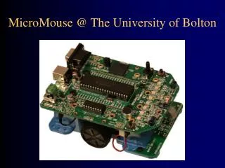
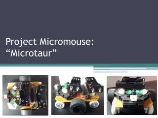
MICROMOUSE 2006. Version: Meat & Potatoes. Aaron Fujimoto. Tyson Seto-Mook. Alex Zamora. Mike Manzano. The Team:. Alex de Angelis. Initial Objectives. Build a wall-hugging mouse -Materials: Sensors: Top down infrared Motors: 1.8 degree stepper motors Processor: Rabbit Card

E N D
MICROMOUSE 2006 Version: Meat & Potatoes
Aaron Fujimoto Tyson Seto-Mook Alex Zamora Mike Manzano The Team: Alex de Angelis
Initial Objectives • Build a wall-hugging mouse -Materials: Sensors: Top down infrared Motors: 1.8 degree stepper motors Processor: Rabbit Card Motor Drivers: The provided Circuit Chassis: Made from sheet metal (Aluminum) -Additional Materials needed (for initial design only): Circuit Boards: Perforated Type Screws for keeping motors and sensor array in place Wheels (expected to come soon) Wire connectors Batteries Resistors, Diodes, solder and other rudimentary parts
The Steps of The Dance… • Build the Chassis. • Complete Sensor array. • Create the Motor Driver Circuit. • Create an effective Tracking algorithm. • Perfect the Tracking algorithm.
Details 2D Plans for Mouse’s Chassis -The Motors are off-center because it is anticipated the batteries will be lighter than the Motors. -Final Mouse will have the center of mass aligned on the axis of the geometric center. -Less Chassis out-front permits a shorter sensor array to detect on-coming walls. -Flaps bend up to hold motor in place
More details: Sensors -Sensors are expected to be on one side only (for wall hugging mouse). -Sensors will originally be aligned as shown in the diagram on a rectangular strip protruding over edge of mouse’s side. -One sensor, possibly two will be out in the front to detect on coming walls. -Other sensors detect side wall. -Sensors will not be soldered onto sensor array, but will be attached via use of connectors. This way any corrections needed will not require resoldering. -Sensors will be adjustable so that their height over the maze’s wall can be adjusted.
Power • 12 V will be needed (of course) • A formal decision on the type of batteries to be employed has not been made -Nickel Metal Hydride (possibility) • For this initial design, battery selection is not of incredible importance, as we expect to upgrade our wall-hugging mouse in order to make it competitive.
Motors & Motor Drivers • As provided by the Kit, 1.8 degree stepper motors will be utilized. • Initially, the tutorial provided Motor driver circuit will be used. • This circuit may be modified in the future following the demonstration of a capable hugger.
The Expected Mouse The diagram does not include a missing frontal sensor (for the purpose of detecting on Coming walls) Also, the diagram does not include the sensor circuitry that will be ON board the mouse
Phase II • Modify the wall Hugging mouse so that it may stand a chance of winning • Several Possibilities for sensory system • Will need a maze solving algorithm • Optimization = Speed
Group Logistics • Meeting Times • Documentation • Division of labor • Portal to the World: our Web Page