Download

1 / 77
800 likes | 855 Views
Image Receptors. Film Construction, Film Handling, Cassette Construction, DarkRoom, Digital Imaging. Week 10. Week 9. Image Receptors. -Review of Primary Beam - Film Construction -Film Handling -Cassette Construction -darkroom. Review of Primary Beam. Primary Radiation exit from tube

E N D
Image Receptors Film Construction, Film Handling, Cassette Construction, DarkRoom, Digital Imaging
Week 10 Week 9 Image Receptors
-Review of Primary Beam-Film Construction-Film Handling-Cassette Construction-darkroom
Primary Radiation exit from tube 100 % enters patient 1% of the exit radiation forms image on cassette below REMNANT Radiation- Attenuated Beam Scatter Radiation-Compton
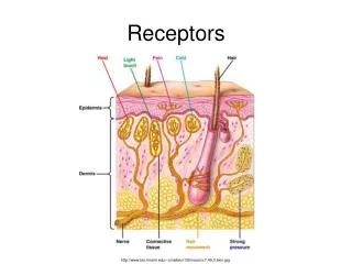
Exit radiation interacts with IMAGE RECEPTOR to capture the image. radiographic image- permanent record of radiation exposed in image receptor latent image -the undeveloped, unprocessed image formed by exit radiation Review of Primary Beam
FIRST “FILM” Glass plates Break easily Difficulty in storage Expensive Cellulose acetate Highly flammable Easily torn
Standard “inches”: 8” x 10” 10” x 12” 11” x 14” 14” x 17” Metric: 18cm x 24cm 24cm x 30cm 30cm x 35cm 35cm x 43cm Film Sizes
Two basic parts: 1. Base 2. Emulsion and Topcoat X-ray Film
Made of a polyester plastic • Must be clear, strong, consistent thickness • Tinted pale blue or blue-gray (reduces eye strain) • Uniform lucency • COATED ON 1 OR 2 SIDES WITH EMULSION Film Construction - BASE
Film emulsion can be on one side or both sides of base (single emulsion / double emulsion) • Protective overcoat layered on top of emulsion-topcoat, supercoat • Emulsion is a gelatin containing the film crystals---THE HEART OF THE FILM Film Construction - EMULSION
Emulsion : • Gelatin with silver halide crystals imbedded • Single or double emulsion, coated on one or both sides of polyester base Topcoat: • Protective layer • AKA supercoat FILM construction-EMULSION
Film Emulsion • Made of mixture of gelatin & silver halide crystals • Silver halide crystals made ofsilver bromide (90%) and silver iodide (10%) • Photographically active layer – activated by light & radiation to create image
Gelatin- comprised of mostly bone, suspends grains (crystals) easily, easily penetrated by processing agents, can be varied in thickness • Silver Halide Crystals- x-ray (silver iodide) and light sensitive (silver bromide) crystals, contains sensitivity speck that reacts to both light and x-ray, this is where latent image is formed, crystals are varying in size, shape, density Emulsion Contents
IMAGE Film Characteristics
Speed – the response to photons, the size and # of crystals and the thickness of emulsion, also known as sensitivity Speed
More silver halide crystals = faster film • Less silver halide crystals= slower film Amount of Crystals
Resolution – the detail seen, depends on the size of the crystals, single or double emulsion (PARALLAX) Resolution- detail
1 2 PARALLAX –each emulsion has an image single image each film has 2 emulsions creating overlapped – edges and a less sharp image 3 Can you name the layers in this image? 4 3 2 1
Film Screen vs. Direct Exposure Imaging Resolution- detail
Line pair resolution test: How many line pairs do you see? What kind of film would Sample A be? What kind of film would Sample B be?
Film Handling Handling and Storage of Films
Light X-rays Gamma Rays Gases Fumes Heat Moisture Pressure Static Electricity Age X-ray Film Sensitivity So what happens??
Improper Film Handling Results in Film Artifacts, Film Fog Artifacts……any unintended positive or negative image on the image receptor not caused by the exit beam, does not contribute to diagnostic image Film Fog……..Unintended uniform optical density on a radiograph, get a long scale of contrast
Clean, dry location • 40 – 60 % Humidity 70 º Fahrenheit • Away from chemical fumes • Safe from radiation exposure • Standing on edge • Expiration date clearly visible Film Storage
Protect film from exposure to light Protect film from bending and scratching during use. May contain intensifying screens, keeps film in close contact to screen during exposure. Cassettes function
Direct x-ray exposure to film: • Requires 25 to 400 times more radiation to create an image on the film • Better detail than film screen (no blurring of image from light) • All exposure made from x-ray photons • Very large dose to the patient Cardboard Cassettes
FILM CASSETTE or FILM HOLDER • The CASSETTE is used to hold the film during examinations. • It consist of front and back intensifying screens, and has a lead (Pb) backing. • The cassette is light tight
Exposure side of cassette is the “front”. • Has the ID blocker (patient identification) • Made of radiolucent material • Intensifying screen mounted to inside of front. Cassette Features - Front
ID blocker FILM ID PRINTER
Cassette Features - Back • Back made of metal or plastic • Inside back is a layer of lead foil – prevents backscatter that could fog the film • Inside foil layer is a layer of padding – maintains good film/screen contact • Back intensifying screen mounted on padding
Polyester plastic base – support layer • Phosphor layer – active layer • Reflective layer – increases screen efficiency by redirecting light headed in other directions • Protective coating Screen Construction
Intensifying Screens • Flat base coated with fluorescent crystals called phosphors • Active layer- (phosphors) give off light when exposed to photons (x-rays)
RARE EARTH – (emits green light) • Developed in 1980’s • Most efficient • Most common in use today • CALCIUM TUNGSTATE (blue light) • Not as efficient • Not used as often Intensifying Screens Phosphors
Gadolinium • Lanthanum • Yttrium • Found in low abundance in nature Rare Earth Screenstwo times faster than calcium tungstate
DISADVANTAGES: • less detail than direct exposure (but detail better with rare earth than calcium tungstate screens) ADVANTAGES: • Reduce patient exposure • Increase x-ray tube life INTENSIFYING SCREENS