Download
1 / 60
3.54k likes | 7.75k Views
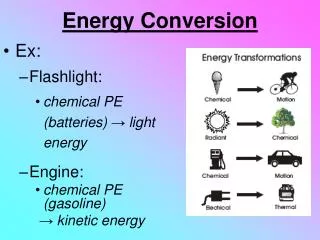
Chapter 2. Electromechanical Energy Conversion. Introduction. Electromechanical energy conversions – use a magnetic field as the medium of energy conversion. Electromechanical energy conversion device:. Converts electrical energy into mechanical energy or

E N D
Chapter 2. Electromechanical Energy Conversion
Introduction Electromechanical energy conversions – use a magnetic field as the medium of energy conversion Electromechanical energy conversion device: Converts electrical energy into mechanical energy or Converts mechanical energy into electrical energy.
Introduction Three categories of electromechanical energy conversion devices: • Transducers (for measurement and control)- small motion Transform the signals of different forms. Examples: microphones, sensors and speakers. • Force producing devices (translational force)- limited mechanical motion. Produce forces mostly for linear motion drives, Example Actuators - relays, solenoids and electromagnets. • Continuous energy conversion equipment. Operate in rotating mode. Examples: motors and generators.
Energy Conversion Process The principle of conservation of energy: Energy can neither be created nor destroyed. It can only be changed from one form to another. Therefore total energy in a system is constant
Energy Conversion Process • An electromechanical converter system has three essential parts: • An electrical system (electric circuits such as windings) • A magnetic system (magnetic field in the magnetic cores and air gaps) • A mechanical system (mechanically movable parts such as a rotor in an electrical machine).
EM Energy Conversion: Analogy Thermal Energy (losses) Electrical Energy (input) Field Energy Mechanical Energy (output)
Electromechanical System Electrical System Magnetic System Mechanical System Voltages and Currents Magnetic Flux Position, Speed and Acceleration Circuit Equations (KVL and KCL) Force/Torque Eqns (Newtons Law) Froce/Torque emf Concept of electromechanical system modeling Energy Conversion Process
Electrical system Magnetic system Mechanical system P mech Electrical loss Field loss Mechanical loss Energy Conversion Process The energy transfer equation is as follows:
Energy Conversion Process The energy balance can therefore be written as: For the lossless magnetic energy storage system in differential form, dWe = i d = differential change in electric energy input dWm = fm dx = differential change in mechanical energy output dWf = differential change in magnetic stored energy
Energy Conversion Process We can write Here e is the voltage induced in the electric terminals by changing magnetic stored energy. Together with Faraday’s law for induced voltage, form the basis for the energy method.
Singly-excited System Energy, Coenergy and Force or Torque
Energy in Magnetic System Consider the electromechanical system below: Axial length (perpendicular to page) = l Schematic of an electromagnetic relay
Energy in Magnetic System The mechanical force fm is defined as acting from the relay upon the external mechanical system and the differential mechanical energy output of the relay is dWm = fm dx Then, substitution dWe = id , gives dWf = id – fm dx Value of Wf is uniquely specified by the values of and x, since the magnetic energy storage system is lossless.
Energy in Magnetic System dWf = idl l dl i dWf = differential change in magnetic stored energy
Energy and Coenergy The l-i characteristics of an electromagnetic system depends on theair-gap length and B-H characteristicsof the magnetic material. For a larger air-gap lengththe characteristic is essentiallylinear. The characteristic becomes non linear as the air-gap length decreases.
Energy and Coenergy For a particular value of air-gap length, the field energy is represented by the red area between l axis and l-i characteristic. The blue area between i axis and l - i characteristic is known as the coenergy
Energy and Coenergy The coenergy is defined as From the figure of l - i characteristic, Wf’ + Wf = l i Note that Wf’ > Wf if the l - i characteristic is non linear and Wf’ = Wf if it is linear. The quantity of coenergy has no physical significance. However, it can be used to derive expressions for force (torque) developed in an electromagnetic system
Determination of Force from Energy The magnetic stored energy Wf is a state function, determined uniquely by the independent state variables λ and x. This is shown explicitly by dWf (λ, x) = id – fm dx
Determination of Force from Energy For any function of two independent variables F(x1,x2), the total differential equation of F with respect to the two state variables x1 and x2 can be written
Determination of Force from Energy Therefore, for the total differential of Wf And we know that
Determination of Force from Energy By matching both equations, the current: where the partial derivative is taken while holding x constant and the mechanical force: where the partial derivative is taken while holding constant.
Determination of Force from Energy: Linear System For a linear magnetic system for which =L(x)i: and the force, fm can be found directly:
Determination of Torque from Energy For a system with a rotating mechanical terminal, the mechanical terminal variables become the angular displacement θ and the torque T. Therefore, equation for the torque: where the partial derivative is taken while holding constant.
Determination of Force from Coenergy The coenergy Wf’ is defined as and the differential coenergy dWf’: We know previously that
Determination of Force from Coenergy By expanding d(iλ): So, the differential coenergy dWf’:
Determination of Force from Coenergy By expanding dWf’(i,x): and, from the previous result:
Determination of Force from Coenergy By matching both equations, : where the partial derivative is taken while holding x constant and the mechanical force: where the partial derivative is taken while holding iconstant.
Determination of Force from Coenergy: Linear System For a linear magnetic system for which =L(x)i: and the force, fm can be found directly:
Determination of Torque from Coenergy For a system with a rotating mechanical terminal, the mechanical terminal variables become the angular displacement θ and the torque T. Therefore, equation for the torque: where the partial derivative is taken while holding constant.
Determination of Force Using Energy or Coenergy? The selection of energy or coenergy as the function to find the force is purely a matter of convenience. They both give the same result, but one or the other may be simpler analytically, depending on the desired result and characteristics of the system being analyzed.
Direction of Force Developed 1. By using energy function: The negative sign shows that the force acts in a direction to decrease the magnetic field stored energy at constant flux. 2. By using coenergy function: The positive sign emphasizes that the force acts in a direction to increase the coenergy at constant current.
Direction of Force Developed 3. By using inductance function: The positive sign emphasizes that the force acts in a direction to increase the inductance at constant current.
B-H Curve and Energy Density and in which In a magnetic circuit having a substantial air gap g, and high permeability of the iron core, nearly all the stored energy resides in the gap. Therefore, in most of the cases we just need to consider the energy stored in the gap. The magnetic stored energy, * Sen pg97 9/8/2014 Dr Awang Jusoh/Dr Makbul 33
B-H Curve and Energy Density Therefore, However, Ag is volume of the air gap. Dividing both sides of the above equation by the volume Ag results in * Sen pg97 9/8/2014 Dr Awang Jusoh/Dr Makbul 34
B-H Curve and Energy Density wf B H where is energy per unit volume wfis known as energy density. The area between the B-H curve and B axis represents the energy density in the air gap. * Sen pg97 9/8/2014 Dr Awang Jusoh/Dr Makbul 35
B-H Curve and Energy Density B wf’ H In the same manner, is coenergy per unit volume. The area between the B-H curve and H axis represents the coenergy density in the air gap. * Sen pg97 9/8/2014 Dr Awang Jusoh/Dr Makbul 36
B-H Curve and Energy Density For a linear magnetic circuit, B = mH or H = B/m, energy density: and coenergy density: In this case, it is obvious that wf = wf’. * Sen pg97 9/8/2014 Dr Awang Jusoh/Dr Makbul 37
Example 3.1 PC Sen • The dimensions of the relay system are shown in figure below. The magnetic core is made of cast steel whose B-H characteristic is shown in Figure 1.7 (pg.6). The coil has 300 turns, and the coil resistance is 6 ohms. For a fixed air-gap length lg = 4 mm, a dc source is connected to the coil to produce a flux density of 1.1 Tesla in the air-gap. Calculate • The voltage of the dc source. • The stored field energy. Pg:99 PC Sen
Example 3.2 PC Sen • The l-i relationship for an electromagnetic system is given by • which is valid for the limits 0 < i < 4 A and 3 < g < 10 cm. For current i = 3A and air gap length g = 5 cm, find the mechanical force on the moving part using coenergy and energy of the field. -124.7 Nm pg103 sen
Example 3.3 PC Sen The magnetic system shown in the Figure has the following parameters: N = 400, i = 3 A Width of air-gap = 2.5 cm Depth of air-gap = 2.5 cm Length of air-gap = 1.5 mm Neglect the reluctance of the core, leakage flux and the fringing flux. Determine: (a) The force of attraction between both sides of the air-gap (b) The energy stored in the air-gap. (c) Coil Inductance Sen pg 106
Example 3.4 PC Sen • The lifting magnetic system is shown, with a square cross section area 6 x 6 cm2. The coil has 300 turns and a resistance of 6 ohms. Neglect core reluctance and fringing effect. • The air gap is initially 5mm and a dc source of 120 V is connected to the coil. Determine the stored field energy and the lifting force • The air gap is held at 5 mm and an ac source of 120 Vrms at 60 Hz is supplied to the coil. Determine the average value of the lift force Sen 107
Example 1 Q. The magnetic circuit shown in Figure Q1 is made of high permeability steel so that its reluctance can be negligible. The movable part is free to move about an x-axis. The coil has 1000 turns, the area normal to the flux is (5 cm 10 cm), and the length of a single air gap is 5 mm. (i) Derive an expression for the inductance, L, as a function of air gap, g. (ii) Determine the force, Fm, for the current i =10 A. (iii) The maximum flux density in the air gaps is to be limited to approximately 1.0 Tesla to avoid excessive saturation of the steel. Compute the maximum force. Immovable part x g Reference position i Fm + e - Spring Movable part
Example 2 Figure below shows a relay made of infinitely-permeable magnetic material with a moveable plunger (infinitely-permeable material). The height of the plunger is much greater than air gap length (h>>g). Calculate a) The magnetic storage energy Wf as a function of plunger position ( 0< x <d) for N = 1000 turns, g = 2 mm, d= 0.15 m, = 0.1 m and i = 10 A. b) The generated force, Fm b)Pg 121/ 132 Fgrld a)Fgrald :pg121
Example 3 The magnetic circuit shown is made of high-permeability electrical steel. Assume the reluctance of steel -- infinity. Derive the expression for the torque acting on the rotor . Fgrd pg 135
Example 4 The magnetic circuit below consists of a single coil stator and an oval rotor. Because of the air-gap is non uniform, the coil inductance varies with the rotor angular position. Given coil inductance L() = Lo + L2cos2, where Lo= 10.6 mH and L2= 2.7 mH. Find torque as a function of for a coil current of 2 A. Fgrd pg 129
Doubly-excited Systems Energy, Coenergy and Force or Torque
Rotating Machines • Most of the energy converters, particularly the higher-power ones, produce rotational motion. • The essential part of a rotating electromagnetic system is shown in the figure. • The fixed part is called the stator, the moving part is called the rotor. • The rotor is mounted on a shaft and is free to rotate between the poles of the stator • Let consider general case where both stator & rotor have windings carrying current ( is and ir )
Rotating Machines • Assume general case, both stator and rotor have winding carrying currents (non-uniform air gap – silent pole rotor) • The system stored field energy, Wf can be evaluated by establishing the stator current is and rotor current ir and let system static, i.e. no mechanical output Stator and rotor flux linkage is expressed in terms of inductances L (which depends on position rotor angle , L()