Download
1 / 9
90 likes | 101 Views
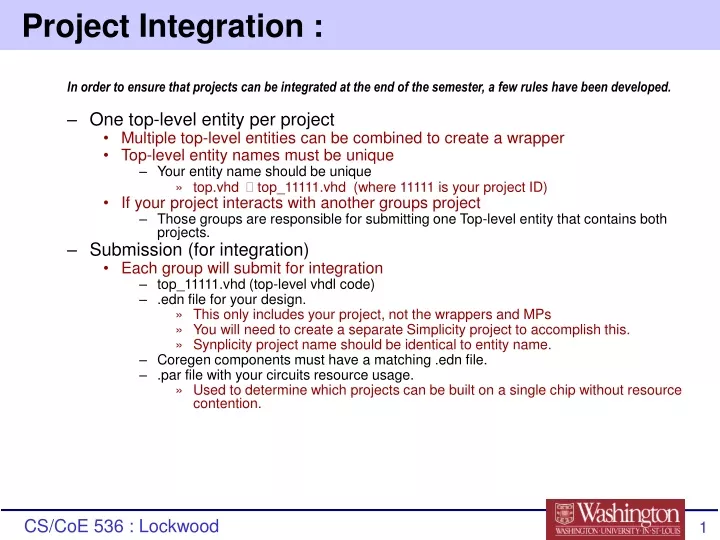
Project Integration :. In order to ensure that projects can be integrated at the end of the semester, a few rules have been developed. One top-level entity per project Multiple top-level entities can be combined to create a wrapper Top-level entity names must be unique

E N D
Project Integration : In order to ensure that projects can be integrated at the end of the semester, a few rules have been developed. • One top-level entity per project • Multiple top-level entities can be combined to create a wrapper • Top-level entity names must be unique • Your entity name should be unique • top.vhd top_11111.vhd (where 11111 is your project ID) • If your project interacts with another groups project • Those groups are responsible for submitting one Top-level entity that contains both projects. • Submission (for integration) • Each group will submit for integration • top_11111.vhd (top-level vhdl code) • .edn file for your design. • This only includes your project, not the wrappers and MPs • You will need to create a separate Simplicity project to accomplish this. • Synplicity project name should be identical to entity name. • Coregen components must have a matching .edn file. • .par file with your circuits resource usage. • Used to determine which projects can be built on a single chip without resource contention.
Block Diagram Example (from DoS Shield) Off-Chip SRAM 2 Off-Chip SDRAM 2 Off-Chip SDRAM 1 Off-Chip SRAM 1 SRAM Controller SDRAM 2 Controller SDRAM 1 Controller SRAM 1 Controller SDRAM Free List Manager # SRAM (0..2) # SDRAM (0..3) SDRAM Free pointers dos_shield_ wire Content- based Match (regex) (MP2) Flow Buffer Expanded CAM-based Firewall (MP1) mux_ rt p p p Head Pointers Tail Pointers p p p Match vector Queue Manager (MP 3) Flow# Scheduler (RR, DRR, 3DQ) Layered Protocol Wrappers = New Connectivity = New Component = Available Interface
How Integration will occur: • Your top-level vhdl code will be parsed to determine your entity’s signal naming convention: • After submitting, you will be presented with a html document that will map you signal names to the interface on the SOC (red bars in SOC diagram). • Your design will automatically become available for distribution upon a complete submission. • Early example of html. • http://www.arl.wustl.edu/projects/fpx/soc/
Current status of Final Project Distribution • Current progress of class distribution for final projects: • FlowBuffer with bidirectional support – Distributed • Wrappers with bidirectional support – Completed • Final Project Test Server – Completed • Perfomance testing of current firewall with real internet traffic. • Results: ~ 60Mbps • New Bi-directional wrappers effects only your bit file and will not be noticeable in your simulations.
VCI – HEC for bi-directional flows • Current make_input_cells does not handle VPI • Bidirectional packets must be edited manually • Adding VPI will invalidate the header checksum • Must replace both atm header words (first two words of each cell). • VPI/VCI = 0x00000320 ; Default (Current Make Cells) • VPI/VCI = 0x00000322 ; Default + PT (Current Make Cells) • VPI/VCI = 0x08000320 ; VPI=128 (Manual change) • HEC IS 3a000000 • VPI/VCI = 0x08000322 ; VPI=128 + PT (Manual change) • HEC IS 34000000 • The PT bit in the atm header specifies the end of an AAL5 frame (in our case a packet). • The last atm cell of every packet must have the PT bit set
Control Port Assignment • Class projects Control Cells ports • Control cells are sent to Destination IP 192.168.30.13 • Projects should not alter controls cells. • Projects do not have to use every (or any) control cell port assigned.
COREgen Components • COREgen components have .edn files separate from the top_11111.edn file (project’s edn file). • Component’s must have unique names • Naming Convention fifo >> fifo_11111 • Will create: • vhdl file called fifo_11111.vhd • edn file called fifo_11111.edn • Only the edn file needs to be submitted for integration.
UDP Wrappers • UDP Wrappers currently have problems with real internet traffic. • Solution: Remove UDP and work at IP level • Complications: • Changing Ports causes UDP checksum error. • Normally the UDP Wrappers would re-compute the checksum automatically • Setting Checksum to zero causes the checksum to be ignored. • If you don’t change the ports than setting the checksum to zero doesn’t apply.
Final Projects Test Bit Server • http://fpx2.arl.wustl.edu/cs536 • Transforms INPUT_CELLS.DAT used in simulation to a suitable format for hardware tests. • Server will not maintain wait statements. • Cells sent in back to back • Available now