Download
1 / 31
340 likes | 473 Views
Chapter 18: Circuits and Circuit Elements. 18.1 Schematic Diagrams and Circuits. Schematic Diagrams If you set up the circuit shown here and made a drawing of it, could some one else copy it? A diagram that shows the construction of an electric circuit is called a schematic diagram.

E N D
18.1 Schematic Diagrams and Circuits Schematic Diagrams • If you set up the circuit shown here and made a drawing of it, could some one else copy it? • A diagram that shows the construction of an electric circuit is called a schematic diagram. • The table in the next slide shows how symbols can be used to show bulbs, wires, a battery, switches, etc.
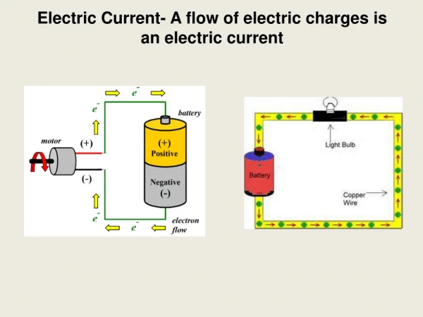
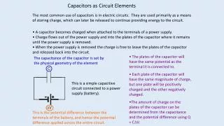
Electric Circuits • The element in a light bulb acts as a resistor. • Because charges are moving through the wire, a current exists. This current causes the filament of the bulb to heat up and glow. • Everything you see here in this photo forms an electric circuit. • When the path from one terminal to the other is complete, a potential difference exists, allowing electrons to move from one terminal to the other. • This is known as a closed-loop or closed circuit. • When there is no charge flow we have an open circuit.
Short circuits can be hazardous • Without a load, such as a light bulb, the circuit contains little resistance to the movement of charges. • This results in a short circuit. • When two un insulated wires touch, a short circuit can occur. • This can allow the wires to over heat and can lead to a fire!
The source of potential difference and electrical energy is the circuit’s emf • A bulb will not light up without a power source like a battery. • It needs a potential difference for charge flow, creating a current. • The battery works as a source of potential difference. • Any device that increases the potential energy of charges circulating in a circuit is a source of electromotive force or “emf”. Also known as a “charge pump”.
For conventional current, the terminal voltage is less than the emf • A battery provides an emf but also contain internal resistance. • Because charges collide with each other as they pass through the battery, resistance results. • The actual terminal voltage is slightly less than the emf. • We will only use terminal voltage to simplify our discussions. • For conventional current, the terminal voltage is less than the emf. There is always a resistance in the battery
Potential difference across a load equals the terminal voltage • As charges move through the circuit, their electrical potential energy is converted to other forms of energy. • For example, when the load is a resistor, the electrical potential energy of the charges are converted to the individual energy of the resistor and dissipated as heat and light. • Because energy is conserved, the energy gained by one complete trip around the circuit must equal the energy dissipated by the bulbs, motors, etc.
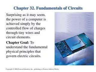
It is a device that contains 3-layers of semiconductors. They can be pnp or npn types. It is like two diodes placed back to back. • What is a transistor? • How do they work? • How are they used in computers? If a small voltage is applied to the middle layer, a large current is allowed. They become switches turning current on and off (binary code) Computers use what is called an integrated circuit. It includes transistors, diodes, capacitors, and resistors all embedded in a single piece of silicon called a “chip”.
Questions1. A diagram that shows the construction of an electric circuit is called a _________ diagram.2. When there is no charge flow we have an ( open / closed) circuit.3.When two un insulated wires touch, a _____ circuit can occur. 4. Any device that increases the potential energy of charges circulating in a circuit is a source of ___________ force or “emf”. 5. Because energy is _________, the energy gained by one complete trip around the circuit must equal the energy dissipated by the bulbs, motors, etc. schematic ____ short electromotive conserved
18.2 Resistors in Series or in Parallel Resistors in Series • In a circuit that contains a single bulb and a battery, the potential difference across the bulb equals the terminal voltage. • This can be calculated using… ΔV=IR • When a second bulb is added, charges that pass through one bulb must equal what pass through the second. • These bulbs are said to be connected in series.
Resistors in series carry the same current • Light bulbs are the same as resistors as the schematic shows below. • Because charge is conserved, the amount of charge that enters one bulb must be the same amount that leaves the other in a given time. • Because of this, the current must be the same for both bulbs. • Even when there are many bulbs, the current in each bulb is the same. • To find the current you first must find the equivalentresistance.
The equivalent resistance in series circuit is the sum of the circuit’s resistances • Using ΔV=IR, the potential difference across each resistor is equal to the current in that resistor multiplied by the resistance. • Our resistors here are in series, so the current in each is the same. • You can treat the circuit as if it has only one resistor or its equivalent… • This formula will allow you to figure out the current or voltage across each resistor.
Practice AResistors in Series • A 9.0 V battery is connected to four light bulbs, as shown here. • Find the equivalent resistance for the circuit. • Find the current in the circuit… For Req = ? use… 2.0Ω + 4.0Ω + 5.0Ω + 7.0Ω = ? Answer 18 Ω
For current in the circuit, I = ? Given: ∆V = 9.0 and Req = 18.0Ω V = IReq answer 0.50 A
Series circuits require all elements to conduct • What happens to a series circuit when a single bulb burns out? • See circuit diagram below… • A broken filament means there is a gap. • Therefore, all bulbs go dark. • Why would anyone want to use this setup? - To regulate current in the device (adding bulbs lowers current in each bulb) - burglar alarms (open window breaks circuit)
Resistors in Parallel • When resistors are placed in this arrangement, alternative pathways for the movement of the charge can occur. • This set up provides alternative pathways and is known as a parallel arrangement.
Resistors in parallel have the same potential difference across them • In this set up, the left side of each bulb is connected to the positive terminal of the battery and the right side to the negative. • Now that the bulbs share a common point, the potential difference (volts) across each bulb is the same. • The potential difference across each bulb is equal to the voltage of the battery.
The sum of the currents in parallel resistors equals the total current • If one of the bulbs has less resistance, more charge moves through that bulb because the bulb offers less opposition to the flow of charges. • Charge is conserved, so the sum of the currents in each bulb equals the current (I) delivered by the battery. • This diagram can be simplified to an equivalent resistance with a method similar to the one used for series circuits. I = I1 + I2
Because the potential difference across each bulb equals the terminal voltage (∆V =∆V1 = ∆V2), you can divide each side of the equation by ∆V to get the following equation; • You must take the reciprocal of your answer to obtain the value of the equivalent resistance. Understand this chart Resistors in Parallel
To help you remember this…For series… current (I) is equal for each resistor, so remember “s-e-r=I=e-s”For parallel… volts (V) are equal for each resistor, so remember “para=V=el”
Practice BResisters in Parallel • A 9.0 volt battery is connected to four resistors, as shown. • Find the equivalent resistance for the circuit. • Find the total current in the circuit. for parallel
For current 0.917 Ω
Given: V = 9.0V Req= 0.917Ω • Unknown: I = ? V = IR answer 9.8 A
Parallel circuits do not require all elements to conduct • When a bulb burns out, each of the parallel branches provides a separate alternate pathway for current. • The potential difference (volts) in the other branches stay the same. • All the resistors wired in parallel maintain the same potential difference as the emf source (battery).
Because household circuits are arranged in parallel, appliances are standardized in their design, allowing all devices to operate at the same potential difference(120 V). • As a result, manufacturers design appliances to ensure that the currents will be neither too high or too low for the internal wiring.
Series Practice 1 answers 2 3
Parallel Practice 1 2 3 answers
Questions1. In ______ circuits, the amount of charge that enters one bulb must be the same amount that leaves the other.2. What happens to a series circuit when a single bulb burns out?3.Resistors placed in this arrangementare called?4. For parallel… _____ are equal for each resistor, so remember “para=V=el”5.T / F Household circuits are arranged in series, allowing all devices to operate at the same voltage of 120. series They all go out parallel volts false