Download
1 / 39
390 likes | 404 Views
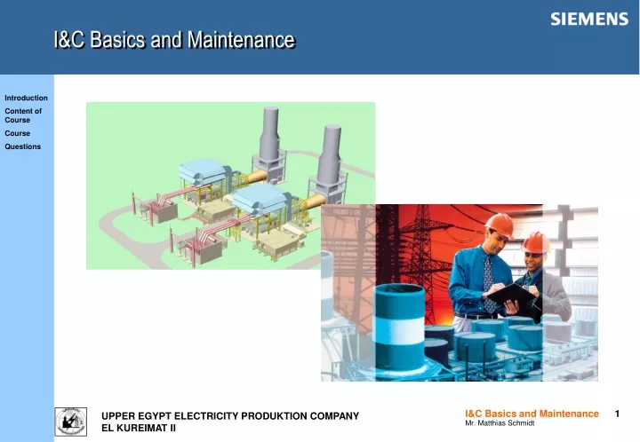
I&C Basics and Maintenance. Introduction. Introduction of the Trainer Mr. Matthias Schmidt I&C scope Scope of maintenance course

E N D
Introduction • Introduction of the Trainer • Mr. Matthias Schmidt I&C scope • Scope of maintenance course • The scope of the maintenance course is to make you familiar with the maintenance and the maintenance documents of the different systems of SIEMENS scope of supply including on site inspections and examples. • The indicated maintenance steps are an extract out of the O&M Manual. They do not describe the overall maintenance of systems en detail and are therefore not binding. This presentation shall be understood as a guideline. • The operation department is responsible for taking plant readings to identify any equipment requiring additional maintenance (e.g. due to high temperature, high vibrations, varying measurements).
Content of course • KKS short description day • ALL Introduction to maintenance and maintenance documentation 1 • ALL General aspects of maintenance 1 • CJP01/02 Basic automation AS620B 1 • CJP41 Failsafe automation AS620F 1 • CJQ01/02 GT measurements 1 • CJR01 Turbine automation AS620T 2 • ES680 Engineering system ES680 2 • OM650 Operation and monitoring system OM650 3 • SGJ/CYE CO2 fire detection / fighting system 3
TXP, a distributed control system for all requirements Operation and management system OM 650 Engineering system ES 680 Diagnostics system DS 670 Process operation Process information Process management Engineering Commissioning Maintenance I&C fault analysis OT OT OT Terminal bus DS OM ES Plant bus Basic automation system AS 620 B Failsafe automation system AS 620 F Turbine automation system AS 620 T SIMATIC S5
M M M M The StructureFrom Complete Overview to the Smallest Detail External Network Router OT OT OT OT OT XU ET DT Process control level Terminal bus SU/PU ES DS Plant bus AP AP AP AP AP Group control level PROFIBUS S5-AG APT S5-AG APF AG-F Individual control level S5 E/A FUM-F SIM-F S5 E/A FUM-B SIM-T PROFIBUS-DP Field level SIMOCODE DP/PA ET200 Positioner DP/ASi PROFIBUS-PA AS-interface
A Function Hierarchy with an increasing density of information
M M M M M AS 620 B Automationstructure with TELEPERM XP Plant bus automation processor AP automation processor AP CM CM mono redundant FUM FUM PROFIBUS-DP Trunk cable SIM main distribution rack switching station IEC 60870 IEC 60870 Remote I/O Modbus Modbus ET 200 ET 200 cable subdistributor Auxiliary Systems SIM = Signal Modules FUM = Function Modules
AS 620B Configuration with redundant APand signal modules SIM-B Plant bus Redundant AP rack (SIMATIC CPU) Fieldbus Distributed peripheral units ET200 Max. 32 ET 200 M stations / AP
AS 620 Clear structure in the standard cabinet Cabinet lamp Transmission module with automatic circuit breakers and suppressor diodes I&C monitor distributing module Shield bar SAE: Cabinet connection elements (as required) Subrack FUM Cable duct for process cable Power bar Subrack redundant AP Diode block with integrated feed-in terminals for redundant 24V DC power supply Cable duct for bus cable
AS 620 Accuracy of time central clock Resolution of time 1 ms Accuracy of time 10 ms (over the system) Resolution of time 1 ms AP Resolution of time 1 ms FUM FUM
Introduction to maintenance • As with any machine gas turbine plants are subject to wear during use. Maintenance is performed to detect and control wear, as well as to repair or replace wear parts as needed to restore wear reserves. With proper maintenance, gas turbine plants can be operated with high reliability and availability. • The manufacturer's maintenance instructions are based on experience gathered with the fleet of gas turbines in service and are updated continually. SIEMENS gas turbine plants are characterized by a straight-forward, maintenance-friendly and robust design, which permits long inspection intervals and minimizes the maintenance effort required. • Maintenance and monitoring are required both during operation and when the unit is at standstill. • Some maintenance work should preferably be performed with the unit at rest, e.g. in the case of any special conditions being noted in the operation log, while other maintenance work may be carried out during normal operation. • “Day-to-day maintenance” or “running maintenance” encompasses all activities which can be performed on the gas turbine and its auxiliary systems without adversely affecting the availability of equipment that is running or on standby. Maintenance includes measures to maintain the specified condition of the plant.
Introduction to maintenance documentation • Operating Manual (Overall Plant) • The Operating Manual contains necessary information for the staff operating the power plant as overall plant. • Operating & Maintenance Documentation (Documents & Data representing Final Layout and Product Handling) • The Operating & Maintenance Documentation comprises technical documents and data required for the description of the set-up and functioning of power plant components and systems, and for their operation and maintenance. • Erection & Commissioning Manuals • Compilation of requirements for the civil engineering, initial erection and initial commissioning of power plants or power plant components. The manuals are prepared for the customer according to PG's scope of supply and services, where appropriate, including the documents from contractors. • Site Documentation • The site documentation comprises the proofs, protocols, certificates etc. arising during initial erection and initial commissioning in the form of quality records (QC). The structuring characteristics are the same as those for the operating & maintenance manuals.
General aspects of maintenance Cabinets / cubicles: • Following activities should be done: • activity recommended interval • - Visual inspection of cabinet (exterior and interior). 6 months • - Check cubicle fan for noise and smooth operation. 6 months • - Check signal lamps and status display. 6 months • - Check cabling, including shielding and earthing, is secure. 6 months • - Check incoming-feeder cable is secure. 6 months • - Check power supply unit and/or feeder diodes. annually • Check cubicle temperature monitor and smoke detector. annually • Grease moving parts. annually • - Check cubicle door contact. annually • - Check supply voltage. annually • Clean cubicle exterior and touch up paint. annually • - Change filter. annually • - Acquire spare parts. annually
General aspects of maintenance Transmitters / transducers: • Following activities should be done: • activity recommended interval • - Visual inspection of device. 6 months • - Check status display. 6 months • Check cabling, including shielding and earthing, is secure. 6 months • Check for ingress of water or moisture. 6 months • Check seals and covers for damage, clean or replace as applicable. 6 months • Check the calibration of device. annually • Clean device exterior and touch up paint. annually • - Acquire spare parts. annually
Maintenance – CJP01/02 – Basic automation AS620B CJP01/02 – Basic automation AS620B (1) • Following activities should be done: • activity recommended interval • - Visual inspection of the cabinet, incl. CPU, modules and terminals. 6 months • - Check the cabling, incl. shielding/strain relief and earthing, is secure. 6 months • - Check the incoming feeder cable is secure. 6 months • Check the fan noise level and that it runs smoothly. 6 months • - Check the supply voltage. 6 months • - Clean or change the air filters. annually *) • - Clean the fans and flow indicators. annually • Check the feeder diodes and the suppressor diodes. annually • Clean the cubicle exterior. annually • Replace the fan. 50.000 hrs. *) • Change the CPU battery. if necessary • *) Or if necessary.
Maintenance – CJP01/02 – Basic automation AS620B CJP01/02 – Basic automation AS620B (2) Following activities should be done: activity recommended interval - Check the I&C ASD in the OM650 system for fault messages. weekly - Check the simulation log in the ES680. weekly - Check for pending code generations and transfers in the ES680 system. weekly
Maintenance – CJP41 – Failsafe automation AS620F CJP41 – Failsafe automation AS620F • Following activities should be done: • activity recommended interval • - Visual inspection of the cabinet, incl. CPU, modules and terminals. 6 months • - Check the cabling, incl. shielding/strain relief and earthing, is secure. 6 months • - Check the incoming feeder cable is secure. 6 months • - Check the fan noise level and that it runs smoothly. 6 months • - Check the supply voltage. 6 months • - Check the feeder diodes and the suppressor diodes. annually • Change the CPU battery. annually *) • Clean the cubicle exterior. annually • *) Or if necessary.
Maintenance – CJQ01/02 – GT measurements CJQ01/02 – GT measurements • Following activities should be done: • activity recommended interval • - Visual inspection of the cabinet, incl. CPU, modules and terminals. 6 months • - Check the cabling, incl. shielding/strain relief and earthing, is secure. 6 months • - Check the incoming feeder cable is secure. 6 months • - Check the fan noise level and that it runs smoothly. 6 months • - Check the supply voltage. 6 months • - Check the feeder diodes. annually • Clean the cubicle exterior. annually • Check and clean the flame scanners. every inspection
Maintenance – CJR01 – Turbine automation AS620T CJR01 – Turbine automation AS620T • Following activities should be done: • activity recommended interval • - Visual inspection of the cabinet, incl. CPU, modules and terminals. 6 months • - Check the cabling, incl. shielding/strain relief and earthing, is secure. 6 months • - Check the incoming feeder cable is secure. 6 months • - Check the fan noise level and that it runs smoothly. 6 months • - Check the supply voltage. 6 months • - Clean or change the air filters. annually • - Clean the fans and flow indicators. annually • Check the feeder diodes and the suppressor diodes. annually • Check the 7-segment indicator for error messages. annually • Check the master function. annually • - Change the CPU battery. 3 years *) • - Clean the cubicle exterior. annually • *) Or if necessary.
Maintenance – CJT – SEE/SFC cubicle CJT – SEE/SFC cubicle • Following activities should be done: • activity recommended interval • - Visual inspection of the cabinet, incl. CPU, modules and terminals. 6 months • Check the cabling, incl. shielding/strain relief and earthing, is secure. 6 months • - Check the incoming feeder cable is secure. 6 months • - Check the fan noise level and that it runs smoothly. 6 months • - Check the supply voltage. 6 months • Oil and grease any mechanically moving parts • (de-excitation switches, door hinges, etc). every inspection • Clean the air filters. annually • Replace the air filters. 5 years • - Replace fan bearings. 50.000 hrs. • Check screws (terminals, busbars etc) 2-3 years • Withdraw and clean the plug-in boards. 5 years • - Function check of all electrical systems by a specialist. 3-5 years
Maintenance – CPA – GT ET200 I/O cubicle CPA – GT ET200 I/O cubicle Following activities should be done: activity recommended interval - Visual inspection of the cabinet, incl. CPU, modules and terminals. 6 months - Check the cabling, incl. shielding/strain relief and earthing, is secure. 6 months - Check the incoming feeder cable is secure. 6 months - Check the fan noise level and that it runs smoothly. 6 months - Check the supply voltage. 6 months - Check the feeder diodes. annually - Check the LED’s on IM314. annually - Clean the cubicle exterior. annually
Maintenance – ES680 – Engineering system ES680 ES680 – Engineering system ES680 • Following activities should be done: • activity recommended interval • Visual check of the computer, keyboard and mouse. 6 months • Visual check of DAT drive. 6 months • Visual check of the mini UPS. 6 months • - Check the fan noise level and that it runs smoothly. 6 months • Check the cabling is secure. 6 months • Check the network interface card / interface module to be tight fit. 6 months • Initiate a self test of the mini UPS. 6 months • Check the night run, DB save. weekly • Signal check of the mini UPS. 6 months • - Save the data onto new tape. 6 months *) • - Clean the computer, keyboard and mouse. annually • Clean the DAT drive. annually • Clean the mini UPS. annually • Replace the accumulator. if necessary • *) Or after the implementation of significant changes.
Maintenance – OM650 – Operation and monitoring system OM650 OM650 – Operation and monitoring system OM650 • Following activities should be done: • activity recommended interval • - Visual check of the computer, keyboard and mouse. 6 months • Visual check of DAT drive. 6 months • Visual check of the mini UPS. 6 months • - Check the fan noise level and that it runs smoothly. 6 months • - Check the cabling is secure. 6 months • Check the network interface card / interface module to be tight fit. 6 months • Initiate a self test of the mini UPS. 6 months • Signal check of the mini UPS. 6 months • - Check the horn module (OT’s). 6 months • - Save the data onto new tape. 6 months *) • - Clean the computer, keyboard and mouse. annually • Clean the DAT drive. annually • Clean the mini UPS. annually • Replace the accumulator. if necessary • *) Or after the implementation of significant changes.
Maintenance – CYQ – Gas Detection System CYQ – Gas Detection System • Following activities should be done: • activity recommended interval • Visual check to determine readiness for operation. daily • Check for correct operation and inspection of Relay Module / Display Card. 3 months • Check for correct operation of Master Card. 6 months • Check connections from transmitters to 8 Ch Display Card. 6 months • Test LED’s and alarm relays of 8 Ch Display Card. 6 months • Check communications between 8 Ch Display Card and module. 6 months • Check signal transmission to controller and alarm triggering for gas detector. 2 years • Calibrate gas detectors. 2 years • Cleaning of gas detector cuvettes . Depending on operating conditions
Maintenance – SGJ / CYE – CO2 fire fighting / detection system SGJ – fire fighting system (1) Following activities should be done: activity recommended interval - Check electrical supply efficiency of fire control system daily - External visual inspection of system components weekly - Check cylinder weights at weighing device weekly - Check external preservation state of piping weekly - Check connection of electrical equipment weekly - Ensure nothing hinders operation of systems monthly - Inspect piping for mechanical damages - Ensure piping securely supported monthly - Check electrical line integrity monthly - Cleaning of components 3 months - Cleaning of CO2 discharge nozzles 6 months - Inspect cylinder banks for tightness, including all mountings 6 months - Inspect cylinders and valves for corrosion or any mechanical damages 6 months - Inspect cylinder straps and outlet fittings for tightness 6 months - Perform functional test of electrical systems 6 months
Maintenance – SGJ / CYE – CO2 fire fighting / detection system SGJ – fire fighting system (2) • Following activities should be done: • activity recommended interval • Perform functional test without discharge. Ensure all audible and annually • visual alarms annunciate, as well as actuation of solenoid valves • of CO2 pilot cylinders • - Purge compressed air into discharge line, checking for obstructions annually • - Clean and tight all electrical terminal fastenings, solenoid valves, annually • pressure and limit switches • - Pressure test for all hose connections 2 years • - Hydrostatic test of cylinders 10 years
Maintenance – SGJ / CYE – CO2 fire fighting / detection system CYE – fire detection system • Following activities should be done: • activity recommended interval • Check the electrical supply efficiency daily • External visual inspection of system components (ctrl panel, sensors, etc) weekly • Check connections of electrical equipment and ascertain good working weekly • order and cleanliness • - Ensure batteries and charger are in good condition weekly • Check warning lights weekly • General inspection monthly • Check integrity of electrical lines monthly • Test alarm and failure simulation monthly • Functional test of electrical system (voltage, continuity and possible grounds) 6 months • Working test of system by acting on elements (pushbuttons, sensors, etc) 6 months • Functional test without discharge annually • Check battery conditions, replace if necessary annually • Replace batteries 5 years