Download
1 / 16
160 likes | 181 Views
Bridge Design Project Design of a Link Bridge over Upper Hanover Street Detailed Design. Group N Chris Jones Ella Feekins Nikoline Hong. Aims and Objectives. To provide a safe passage for pedestrians and cyclists over Upper Hanover Street

E N D
Bridge Design ProjectDesign of a Link Bridge over Upper Hanover StreetDetailed Design Group N Chris Jones Ella Feekins Nikoline Hong
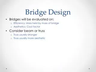
Aims and Objectives • To provide a safe passage for pedestrians and cyclists over Upper Hanover Street • To reduce the use of road level pedestrian crossings, thus improving safety in the area and traffic flow at Brook Hill roundabout • To devise an elegant and sustainable design that will act as a landmark for the University of Sheffield • To provide a direct route between the major university developments
Location • Direct links to major university developments • Does not impede on existing buildings • Requires no permanent road closures • Integrates an existing cycle route • Requires a long span bridge solution
Cable-stayed Bridge • Landmark structure • Integrates into surrounding area • Provides vital links using multiple access points • Incorporates pedestrian footpaths, cycle lanes and disabled access points
Ramp Design • EC3 design • Deck • Simply supported • Typical span 8m • Flexible end plate connections using M20 ‘hollo-bolts’ • Columns • 203x203UC60 sections • Simple connections • Lateral stability provided by diagonal bracing
Ramp Design RAMP ELEVATION
Bridge Deck • Static Analysis Loading: - Permanent: Self weight (including deck plate) - Imposed: 5kN/m2 - Wind: Max 0.8kN/m2 (acting transversely or in uplift)
Bridge Deck • Dynamic Analysis • Simplified model • No mode near pedestrian mode frequencies
Bridge Deck • Thermal Analysis • Bridge deck requires a movement joint • Roller joint will be positioned at one support
Towers • Tower • Designed as 15m cantilever (concrete-filled circular hollow section) • Maximum bending moment 9000kNm at base • Column tapers from 1500mm to 500mm, 25mm wall thickness • No incline due to space issues
Cables and Base • Cables • Maximum cable tension 366kN • Tieback tension 2736kN • 50mm diameter • High tensile strength steel • Bases • Treated as 6m tall, reinforced concrete shell, around base of . tower • Slab: 145 deep, T10 @ 250 centres (T8 @ 300 secondary) • Beams: 500x200, 4T10 bars with T8 links @ 300 centres • Columns: 800x200, 4T10 bars with T8 links @ 300 centres • Assumed to act as an encastre joint for the tower
Construction • Phased construction • Construct reinforced concrete bases • Transport individual prefabricated deck sections to site • Install ramp columns, bracing and deck (giving safe access to tower bases) • Erect support towers • Connect deck sections in series and anchor support cables in tower • Large cranes will be required • Difficult to maintain two lanes of traffic • Temporary stability needs to be provided to bridge deck during construction
Sustainability • Environmental • Durable and low-maintenance design • Limited range of material options • Locally source steel and concrete aggregate • Reduce transport and waste during construction • Provides link to existing cycle path • Social • Provides direct links to major university developments • Incorporates pedestrian footpaths, cycle lanes and disabled access points • Economic • High initial cost may be mitigated using advertising • Low running costs • Encourages improvement in local economy
Conclusion • Landmark Structure • Provides direct links • Socially inclusive