Download
1 / 37
380 likes | 422 Views
Machining Processes Used to Produce Round Shapes. Subject :- Machining Processes Class :- IV th Semester Presented by :- Prof. S. B. Gaikwad. Machining Processes Used to Produce Round Shapes. Various Cutting Operations. Turing – produces straight, conical, curved, or grooved workpieces

E N D
Machining Processes Used to Produce Round Shapes Subject :- Machining Processes Class :- IVth Semester Presented by :- Prof. S. B. Gaikwad
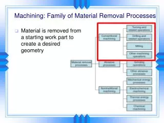
Machining Processes Used to Produce Round Shapes
Various Cutting Operations • Turing – produces straight, conical, curved, or grooved workpieces • Facing – produces a flat surface at the end of the part • Boring – to enlarge a hole • Drilling - to produce a hole • Cutting off – to cut off a workpeiece • Threading – to produce threads • Knurling – produces a regularly shaped roughness
Cutting Operations Fig : Various cutting operations that can be performed on a late. Not that all parts have circular symmetry
Tool Geometry • Rake angle • controls direction of chip flow • Strength of the tool • Side rake angle – • Bake rake angle – controls direction of chip flow • Cutting edges – affects surface finish and tool-tip strength • Nose radius – affects surface finish • Material Removal Rate – (MRR) is the volume of material removed per unit time
Turning Parameters • Forces in turning • Cutting force: acts downward on the tool tip • Thrust force: acts in the longitudinal direction • Radial force: acts in the radial direction • Roughing and Finishing Cuts • Rough cut: high speed cut with little regard for dimensional tolerance • Finishing cut: lower feed rate and depth of cut • Tool Materials, Feeds, and Cutting Speeds • See table 22.4 • Cutting Fluids • See table 22.5
Components of a Lathe Fig : Components of Lathe
Lathes and Lathe Operations • Lathes are the oldest machine tools • Lathe Components • Bed: supports all major components • Carriage: slides along the ways and consists of the cross-slide, tool post, apron • Headstock – Holds the jaws for the work piece, supplies power to the jaws and has various drive speeds • Tailstock – supports the other end of the workpiece • Feed Rod and Lead Screw – Feed rod is powered by a set of gears from the headstock
Lathe Specifications • A lathe is specified by its • Swing – maximum diameter of the workpiece • Distance from headstock and tailstock centers • Length of the bed • Lathes are available in a variety of styles and types of construction power • Types of lathes • Bench lathe: • Placed on a bench • Low power • Hand feed operated • Toolroom lathes: High precision • Engine lathes • Available in a wide variety of sizes • Used for a variety of turning operations
Right Hand Cutting Tool Fig : (a) Designations and symbols for a right-hand cutting tool; solid high-speed-steel tools have a similar designation. Right-hand means that the tool travels from right to left.
Chucks usually equipped with 3 or 4 jaws 3 jaw chucks generally are self centering. Used for round work pieces. Can be centered within .025mm independently. 4 jaw chucks are for square, rectangular, or odd-shaped workpieces Can be power actuated Fig : (a) and (b) Schematic illustrations of a draw-in-type collets. The workpiece is placed in the collet hole, and the conical surfaces of the collet are forced inward by pulling it with a draw bar into the sleeve. (c) A push-out type collet. (d) Workholding of a part on a face plate. Workholding Devices
Mandrels Fig : Various types of mandrels to hold workpieces for turning. These mandrels are usually mounted between centers on a lathe. Note that in (a) both the cylindrical and the end faces of the workpiece can be machined, whereas in (b) and (c) only the cylindrical surfaces can be machined.
Tracer Lathes • Machine tools with attachments • Capable of turning parts with various contours • A tracer finger follows the template and guides the cutting tool Automatic Lathes • Increasingly being automated • Automatic Lathes are suitable for medium to high volume production Automatic Bar Machines • Formerly called automatic screw machines • Designed for high-production-rate machining of screws and other threaded parts • All operations are preformed automatically • Equipped with single or multiple spindles
Turret Lathes Capable of performing multiple cutting operations on the same workpiece • Turning • Boring • Drilling • Thread cutting • Facing Turret lathes are very versatile Types of turret lathes • Ram-type: ram slides in a separate base on the saddle • Saddle type: • more heavily constructed • Used to machine large workpeiceces
Computer Numerical Controls (CNC) Equipped with one or more turrets Each turret is equipped with a variety of tools Performs several operations on different surfaces of the workpiece Fig : A computer numerical control lathe. Note the two turrets on this machine. Computer Numerically Controlled Lathes
Turning Process Capabilities • Production rates • See Table 22.8 • Surface finish and dimensional accuracy Fig : The range of dimensional tolerances obtained in various machining processes as a function of workpiece size. Note that there is an order of magnitude difference between small and large workpieces.
Design Considerations for Turning Operations • Parts should be designed so that can be fixtured and clamped in the work holding devices • Dimensional accuracy and surface finish specified should be as wide as possible • Avoid sharp corners, tapers, and major dimensional variations in the part • Use near-net-shape forming • Cutting tools should be able to travel across workpiece without obstruction • Standard cutting tools, inserts, and toolholders should be used • Materials should be selected for their machineability
Guidelines for Turning Operations • Minimize tool overhang • Support workpiece rigidly • Use machine tools with high stiffness and high damping capacity • When tools begin to vibrate and chatter, modify one or more of the process parameters, such as tool geometry, cutting speed, feed rate, depth of cut, or use of cutting fluid Chip Collection Systems • Drop them on a conveyor belt • Dragging the chips from a setting tank • Using augers with feed screws • Magnetic conveyors • Vacuum methods
High-Speed Machining, Ultraprecision Machining, and Hard Turning • High-Speed Machining • High speed: 600 - 1,800 m/min • Very high speed: 1,800 - 1,800 m/min • Ultrahigh speed: > 18,000 • Important factors • Power and stiffness of the tools • Stiffness of tool holder • Spindle design • Inertia of the machine-tool components • Fast feed drives • Level of automation • Selection of appropriate cutting tool • Ultraprecision Machining – uses a single-crystal diamond, also known as diamond turning • Hard turning • When hardness increases, machinability decreases • Uses polycrystalline cubic boron nitride, cermit, or ceramic cutting tools • Competes successfully with the grinding process
Fig : (a) Standard nomenclature for screw threads, (b) Unified National thread and identification of threads, (c) ISO metric thread and identification of threads. Screw-Thread Nomenclature Standardization of screw threads began in the middle 1880’s Cutting Screw Threads
Cutting Screw Threads • Design Considerations for Screw-Thread Cutting • Should allow for the termination of threads before they reach a shoulder • Eliminate shallow, blind tapped hole • Chamfers should be specified at the ends • Threaded sections should not be interrupted with slots, holes, or other discontinuities • Use standard tooling for threads • Operations should be completed in one step
Cutting Screw Threads Fig : (a) Cutting screw threads on a lathe with a single-point cutting tool. (b) Cutting screw threads with a single-point tool in several passes, normally utilized for large threads. The small arrows in the figures show the direction of feed, and the broken lines show the position of the cutting tool as time progresses. (c) A typical carbide insert and toolholder for cutting screw threads. (d) Cutting internal screw threads with a carbide insert.
Types of Screw threads Fig : Various types of screw threads
Boring • Boring produces circular internal profiles in hollow workpieces • Boring mills are used for large workpieces • Holes can be bored up to 20M if needed • See fig. 22.20 • Machines are available with a variety of features • Horizontal boring machines • Jig borers
Drilling And Drills • Drills • Have high lenth to diameter ratio • Capable of producing deep holes • Some what fexable • Flutes: two spiral grooves that run the length of the drill and allow the chips to escape • Small changes in drill geometry can have a significant effect on the drill’s performance
Drilling And Drills Types of drills • Twist drill: most common drill • Step drill: produces holes of two or more different diameters • Core drill: used to make an existing hole bigger
Drilling And Drills • Drilling operations • Counterboring & countersinking: produce depressions on the surface to accommodate the heads of screws • Center drill: is a short and is used to produce the hole at the end of a piece of stock • Spot drill: is used to spot (start) a hole at the desired location • Gun Drilling - used fro drilling gun barrels and deep holes • Thrust Force and Torque • Thrust force acts perpendicular to the hole axis • Can cause the drill to bend or break if excessive • Drilling Practice • Held in drill chucks • “walking” can be a problem when starting a hole • The drill should be guided • Used a center drill to start a hole • Drills can be reconditioned • Drill life is measured by the number of holes drilled.
Drill point Geometries Fig : Standard chisel-point drill indicating various features. The function of the pair of margins is to provide a bearing surface for the drill against walls of the hole as it penetrates into the workpiece; drills with four margins (double-margin) are available for improved drill guidance and accuracy. Drills with chip-breaker features are also available. (b) Crankshaft-point drill. (c) Various drill points and their manufacturers: 1. Four-facet split point, by komet of America. 2. SE point, by Hertel. 3.New point, by Mitsubishi materials. 4. Hosoipoint, by OSG Tap and Die. 5. Helical point.
Reaming And Reamers • Operation used to make an existing hole dimensionally more accurate than by drilling alone • The hole making sequence is • Centering • Drilling • Boring • reaming Fig : various types of drilling and reaming operations.
Gun Drilling Fig : (a) A gun drill showing various features. (b) method of gun drilling.
Trepanning Fig : (a) trepanning tool (b) trepanning with drill mounted single cutter.
Drilling Machines Fig : Schematic illustration of the components of (a) a vertical drill press and (b) a radial drilling machine.
CNC Milling Machine Fig : A three axis computer numerical control drilling machine. The turret holds as much as eight different tools, such as drills, taps, and reamers.
Reamers Fig : Various types of drilling and
Tapping And Taps • Internal threads in workpiceces can be produced by “tapping” • A tap is a chip-producing threading tool • Tapping may be done by hand or • Drilling machines • Lathes • Automatic screw machines • Vertical CNC milling machines
Tapping and Taps Fig : (a) Terminology for a Tap (b) Tapping of steel nuts in production