Download
1 / 71
720 likes | 746 Views
Capacitors. OBJECTIVES. Become familiar with the basic construction of a capacitor and the factors that affect its ability to store charge on its plates . Be able to determine the transient ( time-varying ) response of a capacitive network and plot the resulting voltages and currents .

E N D
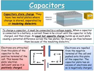
OBJECTIVES • Become familiar with the basic construction of a capacitor and the factors that affect its ability to store charge on its plates. • Be able to determine the transient (time-varying) response of a capacitive network and plot the resulting voltages and currents. • Understand the impact of combining capacitors in series or parallel and how to read the nameplate data. • Develop some familiarity with the use of computer methods to analyze networks with capacitive elements.
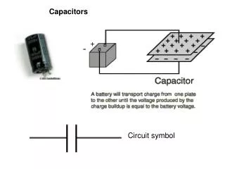
INTRODUCTION • The capacitor has a significant impact on the types of networks that you will be able to design and analyze. • Like the resistor, it is a two-terminal device, but its characteristics are totally different from those of a resistor. • In fact, the capacitor displays its true characteristics only when a change in the voltage or current is made in the network.
FIG. 10.1 Flux distribution from an isolated positive charge. THE ELECTRIC FIELD • Electric field (E) ⇨electric flux lines ⇨ to indicate the strength of E at any point around the charged body. • Denser flux lines ⇨ stronger E.
FIG. 10.2 Determining the force on a unit charge r meters from a charge Q of similar polarity. THE ELECTRIC FIELD
FIG. 10.3 Electric flux distributions: (a) opposite charges; (b) like charges. THE ELECTRIC FIELD • Electric flux lines always extend from a +ve charged body to a -ve charged body, ⊥ to the charged surfaces, and never intersect.
FIG. 10.4 Fundamental charging circuit. CAPACITANCE ⇨V=IR
FIG. 10.7 Effect of a dielectric on the field distribution between the plates of a capacitor: (a) alignment of dipoles in the dielectric; (b) electric field components between the plates of a capacitor with a dielectric present. CAPACITANCE
TABLE 10.1 Relative permittivity (dielectric constant) Σr of various dielectrics. CAPACITANCE
FIG. 10.9 Example 10.2. CAPACITOR Construction ⇨ R =ρL/A
FIG. 10.11 Symbols for the capacitor: (a) fixed; (b) variable. CAPACITORSTypes of Capacitors • Capacitors, like resistors, can be listed under two general headings: fixed and variable.
FIG. 10.12 Demonstrating that, in general, for each type of construction, the size of a capacitor increases with the capacitance value: (a) electrolytic; (b) polyester-film; (c) tantalum. CAPACITORSTypes of Capacitors
FIG. 10.20 Variable capacitors: (a) air; (b) air trimmer; (c) ceramic dielectric compression trimmer. [(a) courtesy of James Millen Manufacturing Co.] CAPACITORSTypes of Capacitors • Variable Capacitors • All the parameters can be changed to create a variable capacitor. • For example; the capacitance of the variable air capacitor is changed by turning the shaft at the end of the unit.
FIG. 10.21 Leakage current: (a) including the leakage resistance in the equivalent model for a capacitor; (b) internal discharge of a capacitor due to the leakage current. CAPACITORSLeakage Current and ESR
FIG. 10.23 Various marking schemes for small capacitors. CAPACITORSCapacitor Labeling
FIG. 10.24 Digital reading capacitance meter. (Courtesy of B+K Precision.) CAPACITORSMeasurement and Testing of Capacitors • The capacitance of a capacitor can be read directly using a meter such as the Universal LCR Meter.
FIG. 10.26 Basic R-C charging network. TRANSIENTS IN CAPACITIVE NETWORKS: THE CHARGING PHASE • The placement of charge on the plates of a capacitor does not occur instantaneously. • Instead, it occurs over a period of time determined by the components of the network.
FIG. 10.27 vC during the charging phase. TRANSIENTS IN CAPACITIVE NETWORKS: THE CHARGING PHASE The current ( ic ) through a capacitive network is essentially zero after five time constants of the capacitor charging phase.
FIG. 10.28 Universal time constant chart. TRANSIENTS IN CAPACITIVE NETWORKS: THE CHARGING PHASE
TABLE 10.3 Selected values of e-x. TRANSIENTS IN CAPACITIVE NETWORKS: THE CHARGING PHASE
TRANSIENTS IN CAPACITIVE NETWORKS: THE CHARGING PHASE • The factor t, called the time constant of the network, has the units of time, as shown below using some of the basic equations introduced earlier in this text:
FIG. 10.29 Plotting the equation yC =E(1 –e-t/t) versus time (t). TRANSIENTS IN CAPACITIVE NETWORKS: THE CHARGING PHASE
FIG. 10.31 Demonstrating that a capacitor has the characteristics of an open circuit after the charging phase has passed. TRANSIENTS IN CAPACITIVE NETWORKS: THE CHARGING PHASE
FIG. 10.32 Revealing the short-circuit equivalent for the capacitor that occurs when the switch is first closed. TRANSIENTS IN CAPACITIVE NETWORKS: THE CHARGING PHASE
FIG. 10.35 Transient network for Example 10.6. TRANSIENTS IN CAPACITIVE NETWORKS: THE CHARGING PHASEUsing the Calculator to Solve Exponential Functions
FIG. 10.36 vC versus time for the charging network in Fig. 10.35. TRANSIENTS IN CAPACITIVE NETWORKS: THE CHARGING PHASEUsing the Calculator to Solve Exponential Functions
FIG. 10.37 Plotting the waveform in Fig. 10.36 versus time (t). TRANSIENTS IN CAPACITIVE NETWORKS: THE CHARGING PHASEUsing the Calculator to Solve Exponential Functions
FIG. 10.38 iC and yR for the charging network in Fig. 10.36. TRANSIENTS IN CAPACITIVE NETWORKS: THE CHARGING PHASEUsing the Calculator to Solve Exponential Functions
TRANSIENTS IN CAPACITIVE NETWORKS: THE DISCHARGING PHASE • How to discharge a capacitor and how long the discharge time will be. • You can, of course, place a lead directly across a capacitor to discharge it very quickly—and possibly cause a visible spark. • For larger capacitors such those in TV sets, this procedure should not be attempted because of the high voltages involved.
FIG. 10.39 (a) Charging network; (b) discharging configuration. TRANSIENTS IN CAPACITIVE NETWORKS: THE DISCHARGING PHASE • For the voltage across the capacitor that is decreasing with time, the mathematical expression is:
FIG. 10.40 yC, iC, and yR for 5t switching between contacts in Fig. 10.39(a). TRANSIENTS IN CAPACITIVE NETWORKS: THE DISCHARGING PHASE
FIG. 10.41 vC and iC for the network in Fig. 10.39(a) with the values in Example 10.6. TRANSIENTS IN CAPACITIVE NETWORKS: THE DISCHARGING PHASE
TRANSIENTS IN CAPACITIVE NETWORKS: THE DISCHARGING PHASEThe Effect of on the Response
FIG. 10.43 Effect of increasing values of C (with R constant) on the charging curve for vC. TRANSIENTS IN CAPACITIVE NETWORKS: THE DISCHARGING PHASEThe Effect of on the Response
FIG. 10.44 Network to be analyzed in Example 10.8. TRANSIENTS IN CAPACITIVE NETWORKS: THE DISCHARGING PHASEThe Effect of on the Response
FIG. 10.45 vC and iC for the network in Fig. 10.44. TRANSIENTS IN CAPACITIVE NETWORKS: THE DISCHARGING PHASEThe Effect of on the Response
FIG. 10.46 Network to be analyzed in Example 10.9. FIG. 10.47 The charging phase for the network in Fig. 10.46. TRANSIENTS IN CAPACITIVE NETWORKS: THE DISCHARGING PHASEThe Effect of on the Response
FIG. 10.48 Network in Fig. 10.47 when the switch is moved to position 2 at t =1t1. TRANSIENTS IN CAPACITIVE NETWORKS: THE DISCHARGING PHASEThe Effect of on the Response
FIG. 10.49 vC for the network in Fig. 10.47. TRANSIENTS IN CAPACITIVE NETWORKS: THE DISCHARGING PHASEThe Effect of on the Response
FIG. 10.50 ic for the network in Fig. 10.47. TRANSIENTS IN CAPACITIVE NETWORKS: THE DISCHARGING PHASEThe Effect of on the Response
FIG. 10.51 Defining the regions associated with a transient response. INITIAL CONDITIONS • The voltage across the capacitor at this instant is called the initial value, as shown for the general waveform in Fig. 10.51.
FIG. 10.52 Example 10.10. INITIAL CONDITIONS
FIG. 10.53 vC and iC for the network in Fig. 10.52. INITIAL CONDITIONS
FIG. 10.54 Defining the parameters in Eq. (10.21) for the discharge phase. INITIAL CONDITIONS
THÉVENIN EQUIVALENT: t =RThC • You may encounter instances in which the network does not have the simple series form in Fig. 10.26. • You then need to find the Thévenin equivalent circuit for the network external to the capacitive element.
FIG. 10.56 Example 10.11. THÉVENIN EQUIVALENT: t =RThC
FIG. 10.57 Applying Thévenin’s theorem to the network in Fig. 10.56. THÉVENIN EQUIVALENT: t =RThC
FIG. 10.58 Substituting the Thévenin equivalent for the network in Fig. 10.56. THÉVENIN EQUIVALENT: t =RThC