Download
1 / 29
290 likes | 429 Views
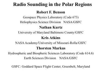
RADIO SOUNDING IN THE MAGNETOSPERE AND TOPSIDE IONOSPHERE. BW Reinisch 1 , DM Haines 1 , RF Benson 2 , K Bibl 1 , G Cheney 1 , SF Fung 2 , J Grebowsky 2 , JL Green 2 , X Huang 1 , R Manning 3 , and WWL Taylor 4 1- University of Massachusetts Lowell, 2- NASA Goddard Space Flight Center,

E N D
RADIO SOUNDING IN THE MAGNETOSPERE AND TOPSIDE IONOSPHERE BW Reinisch1, DM Haines1, RF Benson2, K Bibl1, G Cheney1, SF Fung2, J Grebowsky2, JL Green2, X Huang1, R Manning3, and WWL Taylor4 1- University of Massachusetts Lowell, 2- NASA Goddard Space Flight Center, 3- Observatoire Paris-Meudon, 4- Raytheon STX Deutsche URSI Tagung Kleinheubach 28. September 1998
Space WeatherConnection • Solar Wind Effects • Changing Magnetopause • Changing Plasmasphere • High Latitude Ionosphere
OUTLINE • The IMAGE Mission and RPI • http://image.gsfc.nasa.gov • http://ulcar.uml.edu/rpi • The WARNING Mission and TOPADS • http ://www.rada.kiev.ua
IMAGE Instruments • Neutral Atom Imagers • High Energy Neutral Atom (HENA) imagers • Medium Energy Neutral Atom (MENA) imagers • Low Energy Neutral Atom (LENA) imagers • FUV Imagers • Spectrographic Imager (SI) • Geocorona (GEO) imager • Wideband Imaging Camera (WIC) • EUV Imager • Extreme Ultra-Violet (EUV) imager • Radio Sounder • Radio Plasma Imager (RPI)
Spectrographic Imager (SI) • SI Observations • Far ultraviolet imaging of the aurora • Image full Earth from apogee • Measurement Requirement • FOV: 15°x 15° for aurora (image full Earth from apogee), • Spatial Resolution: 90 km • Spectral Resolution (top): Reject 130.4 nm and select 135.6 nm electron aurora emissions. • Spectral Resolution (bottom): 121.6 nm • Storm/substorm Observations • Image Time: 2 minutes generating 720 images/day • Derived Quantities • Structure and intensity of the electron aurora (top) • Structure
Simulated RPI Plasmagram • RPI browse product data will produce plasmagrams • Echoes shown in solid line, density features in dashed line. • Derived Quantities from Plasmagrams include: • Distance to Magnetopause, Plasmapause, Polar Cusp (when observed) • Magnetospheric shape (with model), structure, gross irregularities • Storm conditions from a plasma/radio wave perspective
RPI Waveforms • short pulse (3.2 ms) • long pulse (125ms) • half-sec pulse • 2-sec pulse • n-chip complimentary phase codes,n=4,8,16 • chirp pulse (125 ms) • staggered pulse sequence (768 chips)
RPI Operational Modes • Echo Sounding w. Antenna Tuning • Relaxation w/o Antenna Tuning • Whistler Excitation (transmit f, receive diff. f’s) • Thermal Noise Passive Reception
+Z +X +Y Radio Imaging E’ E Electric Field Ellipse E’ is phase quadrature sample of E E x E’ E-Plane Normal = EE’ E2 + E'2 Echo Amplitude = Polarization = Direction of E-Plane Normal
Topside Sounding - 1971 ISIS Topside Ionogram showing Plasma Resonance Modes Plasma resonance frequencies provide In-situ Ne and Magnetic Field Intensity Remote echoes provide vertical Ne profiles fN = O-mode Plasma Resonance fH = Gyro Resonance fT = Upper Hybrid Resonance fX = X-mode Plasma Resonance fZ = Z-mode Plasma Resonance
TOPADS Signal Processing • High receiver sensitivity - 125 nV • pulse compression - compl. phase code • spectral coh. integration - ±1 kHz, 0.1 Hz res. • chirping
Transmitted Pulses and Raw Echoes (PRR = 100 Hz) Received Echoes after Compression (Effective PRR = 50 Hz) Complementary CodePulse Compression
Sum CODE 1 + CODE 2 Code 1 Code 2 Result Signal Processing Gain = 15 db.
Doppler Integration(8 Complementary Pulse Pairs, 1 Frequency, 2 Polarizations, 200 Hz PRR) Echoes from 8 pulses Spectrum at 300 km Signal Processing Gain = 9 db.
Actual Doppler SpectraMillstone Hill - CORIS DPS1 30-Jun-1997(Courtesy of Alain Thomas)