Download
1 / 21
210 likes | 343 Views
Mechanical Properties of Roebel Coated Conductor Cable. Kario 1 , S. Otten 1,2 , C. M. Bayer 1 , M. Vojenciak 1,3 , A. Kling 1 , B . Ringsdorf 1 , B. Runtsch 1 , W. Goldacker 1 1 Karlsruhe Institute of Technology, Institute for Technical Physics

E N D
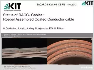
Mechanical Properties of Roebel Coated Conductor Cable Kario1, S. Otten1,2, C. M. Bayer1, M. Vojenciak1,3, A. Kling1, B. Ringsdorf1, B. Runtsch1, W. Goldacker1 1Karlsruhe Institute of Technology, Institute for Technical Physics 2 University of Twente, Chair of Energy, Materials and Systems 3Institute of Electrical Engineering, Slovak Academy of Science
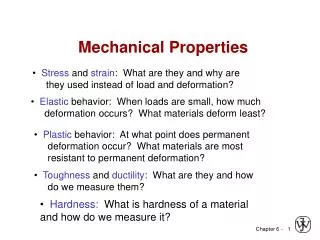
Motivation forces field current G. Kirby et al., EuCARDII Meeting • Bending properties • Tensile stress • Transverse stress • Need of impregnation
Outline Tensile stress Bending properties Transversal stress Impregnation
Bending radii > 10 mm do not degrade the Ic Cable geometry: 12 mm cable, 10 strands, TL: 126 mm Measurements on single strands show degradation in the bent section by < 1% Small degradation, < 6.5 % of total cable Ic Cable degradation was not caused by bending r = 50 mm r = 10 mm To be published
Roebel cable is fragile to bending-torsion Cable 10 or 15 mm diameter • 5% or 10% degradation at 20° winding angle • No reversibility in a case of 10 and 15 mm thickness
Outline Bending properties Tensile stress Transversal stress Impregnation
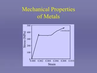
Modelling of the stress in meander structure C. Barth et al., Supercond. Sci. Technol. 25 (2012) 025007 (9pp) • 4 mm Roebel cable • Superpower tape: 100 µm thick, Yong modulus: 120 GPa • Applied tensile load 1 kN • Finite Element Method, ComsolMultiphysics
Roebel strand geometry: outer corner and 10 mm inner radius • High von Mises stress – concentrated in small areas, favour the growth of cracks • Low von Misesstress – distributed over large area, cable can withstand high tensile load C. Barth et al., Supercond. Sci. Technol. 25 (2012) 025007 (9pp)
Outline Bending properties Tensile stress Transversal stress Impregnation
Different compressive stress values 10 – 40 MPa J. Fleiteret al., Supercond. Sci. Technol. 26 (2013) 065014 (5pp) D. Ugliettiet al., Supercond. Sci. Technol. 26 (2013) 074002 (5pp) • GCS cable: 15 strands, TL: 300 mm • Effective stress: 111 MPa (36% surface) • degradation of the individual strands Ic • by 30% at a transverse stress of 10 MPa. • KIT cable: 10 strands, TL: 126 mm • Effective stress: 167 MPa (24% surface)
Transversal stress test with additional copper strands stainlesssteel Roebelstrands Copperstrands • Contact area of stainless steel: 4 mm x 85 mm
5% Ic degradation by 68.8 MPa effective stress • Average transverse stress (cable surface) • Effective transverse stress To be published
Defects on theRoebel-bridge Magneto-optical Imaging 60 K, 20 mT 61 K, 30 mT 2 mm 2 mm 2 mm • Icmeasurements after deassemblyofthe • Roebelcable 60 K, 25 mT To be published
Outline Bending properties Tensile stress Transversal stress Impregnation
Epoxy choice Commercially available resins with fillers Thermal expansion Thermal conductivity Chemical compatibility with REBCO Resin working temperature Resin viscosity Low Tc cable example Fred M. Asner, High Field SuperconductingMagnets, CLARENDON PRESS OXFORD 1999 Stress concentrations
Thermal expansion similar to REBCO for more then 50% filled epoxy's Thermal expansion (%) * * * * N. Bagrets, ITEP, KIT Thermal expansion < 0.7 % preferred To be published * C. Barth,PhDthesis (2013)
Equal thermal conductivity at 4.2 K for silica and alumina filled epoxy's λ (W/ m*K) λ (W/ m*K) * * * 4.2 K 300 K * * * S. Drotziger, ITEP, KIT At 4.2 K, all epoxies have very low thermal conductivity Effect of fillers is small compared to 77-300 K To be published * C. Barth, PhD thesis (2013)
Impregnation of dummy Roebelcables • Wet-winding • Vacuum impregnation with fused silica • Vacuum impregnation with fused silica and glass fibre To be published
Vacuum impregnation with Araldite and 50% fused silica • Dummy between two stainless steel tapes • Araldite CY5538/HY5571 with 50 wt% fused silica • T = 80 °C, P = 0.3 kPa • Thickness < 1 mm → high current density Epoxy filledcentral hole 100 µm stainless steel tape • Dummy with one SP REBCO strand • Ic measurement at 77 K • No Ic degradation To be published
Transverse pressure tests (U. Twente) Samples to be tested Reference cable Impregnated cable(CY5538/HY5571 + 50 wt% silica) Cryogenic press (UTwente) T = 4.2 K Imax = 50 kA Bmax = 11 T (perpendicular) Fmax = 260 kN U-shaped samples W. Van de Camp, master thesis, University of Twente, 2012
Summary • Bending • Easy direction down to 10 mm radius: TL:126 mm, 10 strands cable • Depends on: TL, no. of tapes, SC tape • Tensile stress • Optimised structure: outer corner, • inner radius 10 mm (fixed) • Transverse stress • Impregnation support needed • Impregnation • Vacuum impregnation with Araldite 50% fused silica proposed ? Bending properties Tensile stress ? ? ? ? ? Transversal stress Impregnation