Download
1 / 20
200 likes | 331 Views
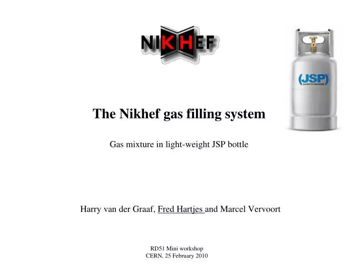
The Nikhef gas filling system Gas mixture in light-weight JSP bottle. Harry van der Graaf, Fred Hartjes and Marcel Vervoort. RD51 Mini workshop CERN, 25 February 2010. Why using premixed gases in JSP bottle?. No need for gas mixing system on site Content 12.3 l Pressure up to 20 bar gauge

E N D
The Nikhef gas filling systemGas mixture in light-weight JSP bottle Harry van der Graaf, Fred Hartjes and Marcel Vervoort RD51 Mini workshop CERN, 25 February 2010
Why using premixed gases in JSP bottle? • No need for gas mixing system on site • Content 12.3 l • Pressure up to 20 bar gauge • Useful for small flows (like 0.1 – 1.0 l/h) • => running time 10 – 100 days • Relaxed safety requirements • When filled with flammable mixture less dangerous than a simple spray can • Possibly may be placed in test beam area • => short and thin pipes, low dead volume • Using premixed from commercial vendors not attractive • Expensive • Long delivery time (5 – 6 weeks) • => We built a gas filling system in house (Nikhef)
Gas bottle Empty weight 4.1 kg 475 mm • Volume: 12.3 l • Special version of light weight bottle • Fabricate JSP • Originally intended for butane and propane • Material: AISI 304 (stainless steel) • Test pressure: 30 bar • Burst pressure: 140 bar • Controlled burst location (cylinder bottom) • Equipped with safety valve opening at 27 bar gauge • => good filling pressure: 20 bar gauge • Seals of outlet valve and safety valve: NBR (nitrile) • Outlet valve: only gas exposure to metals when closed • Valve thread for regulator: LU-1 (W21,8x1/14"L) • (commonly used left thread for flammable gases)
Certificates • TPED 1999/36 (pi) • EN14140 • ADR (international transport of dangerous goods by rail) • RID (international transport of dangerous goods by train) • IMDG (international marine code of dangerous goods) • RRP (pressure container regulation) • RAP (pressure machine regulation) • Certified to conform to EN 14140; Directive (ADR) 94/55/EC and Directive (TPED) 99/36/EC • All certificates apply for bottle filled with liquefied flammable gas • LPG, Butane, Propane
Diagram Nikhef gas filling system Computer controlled (LabView) gas mixing by pressure monitoring Using accurate (+/-35 mbar) electronic pressure sensor Mixtures with up to 3 components
Planned filling sequence • Put required mixture in LabView sequencer • Partial pressures will be calculated • Evacuate bottle and tubing to < 1 mbar • Fill to ~ 1 bar abs with “background” gas (argon, CO2, He, N2, ......) • Re-evacuate • Fill with component 1 to desired partial pressure and stop automatically • Measure obtained pressure after few minutes • Add component 2 to desired summed pressure and stop automatically • Measure obtained pressure • Even so for component 3 • Calculate obtained mixing ratio • Print bottle label and write data in log file
Vapour pressures vs temperature • Maximum bottle pressure often determined by condensation point • Isobutane 2.6 bar @ 15 ºC • => Ar/iC4H10 50/50 can be no more than 5.2 bar abs or 4.2 bar gauge • DME 5.1 bar @ 20 ºC • Boiling point – 24.8 ºC
Expected performance • Accuracy of the component fraction 0.1% of total mixture • Deviation from required mixture 1% of total mixture • Example: • Target mixture Ar/CH4 90/10 • Realized mixture will be something like Ar/CH4 (90.08±0.1)/(9.92±0.1) • Contamination • O2, N2, H2O on ppM level • To be confirmed • There will be no independent analysis of the mixture or to traces of contamination • Measuring oxygen on ppM level might be possible
Possible contamination by materials filling system • Gas bottle • Stainless steel AISI 304 • Valves • NBR • Teflon tape • ..................... • Piping, fittings • stainless steel • Cleaning • Piping, fittings: well cleaned • Gas bottle • Etched, flushed and neutralised after high temperature manufacturing • Baking out not standard but possible (130 °C under vacuum) • High temperature baking (300 – 800 °C possible when dismantling valve • => for critical operation adequate filtering (molecular sieve) mandatory • ageing tests
Security rules for the gas mixing station at Nikhef • Creating mixtures with flammable gases at Nikhef allowed if • Done in well vented space • Explosion detection available • Proper grounding of equipment • Only accessible for limited number of persons • These persons are well trained • Additional fire extinguisher is present • Risk analysis has been made • Flammable gas indication is outside • Security staff has been informed and instructed
Pressure of DME and isobutane mixtures limited by vapour pressure Using JSP bottle with flammable gas mixtures at a CERN test beam
Safety in perspective 50 l bottle with isobutane ~6750 g Heq Spray can/lighter filler 68.4 g Heq Butane container for cooking ~2500 g Heq • JSP bottle accepted in beam area? • JSP bottle may be safely transported in a car • Airplane Premixed JSP bottle with DME/CO2 50/50 25.5 g Heq
Using JSP bottles with flammable mixture at CERN • Not more than ~ 30 g Heq • Well within Risk Class 1 (< 400 g Heq) • One should wish having another Risk Class (< 40 g Heq) • Range of spray can
Commissioning • Gas heated by filling process • Cooled by wall of bottle • Bottle temperature stabilized by water • Double exponential decay to saturation value • t = 36 s and ~ 4 min • After 2 min within 0.1% limit
Present status 22-2-2010 • Finished • Hardware installation • Remote control operational • Electromagnetic valves • Vacuum pump • Pressure meter • To be done • Commissioning • Operation program (LabView) • Sequencing • Logging • CE certification
Conclusions • Using premixed gases in JSP bottles has many advantages for low (< 1 l/h) flow applications • Thin gas pipes (1/8”) • Premix gas bottles in lab/ test beam area • Simple, non critical (1 channel) gas regulation • Easy and cheap experimental set-up • Nikhef installation will be soon ready to fill the JSP bottles
Test beam gas system with premixed bottles • Assume small flow (≤ 0.3 l/h) • Flow regulated by electronic mass flow controller (explosion proof) • Flow check (electronic mass flow sensor) at exhaust • => verifying leaks • Upstream: thin pipes may be used (1/8”, 1/16”, 1/32”) • Downstream: thicker pipes (1/8”)
What is different for single chip MPGDs? • Very small detector volumes • 1 Gossip detector ≈ 0.2 ml (15 x 15 x 1 mm3) • => very small gas flows may be used • 10 volume changes/hour • => 33 µl/min (2 ml/h) • Commercial mass flow controllers go down to ~ 2 ml/min FS • => permit flows down to 100 µl/min • For practical reasons we normally use bit larger flows • 2 - 5 ml/min (0.12 – 0.3 l/h)
Advantages of small flows (0.12 – 0.3 l/h) 1/32” tubing • Permitting very thin gas lines • Gas lines 1/32” (≈ 0.8 mm OD) well feasible • 3 m tubing 0.5 mm ID with CO2 and 0.12 – 0.3 l/h • => Back pressure 10 – 24 mbar • Gas line of 1/64” (≈ 0.4 mm OD) not excluded • 3 m tubing 0.25 mm ID with CO2 and 0.12 – 0.3 l/h) • => Back pressure 0.15 – 0.4 bar • (Using normal size gas pipes (6 mm OD or larger) would lead to very long reaction times) • On site mixing of small flows hard • Long flow measurement times • (almost) out of range of commercial mass flow controllers • => use premixed gas bottles