Download
1 / 114
1.28k likes | 1.72k Views
CHAPTER 13. Wired LANs: Ethernet. شبكات الاتصال المحلية السلكية (الايثرنت ). المهندسة : بنان عبد الكريم محمودي. introduction.

E N D
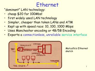
CHAPTER 13 Wired LANs: Ethernet شبكات الاتصال المحلية السلكية (الايثرنت ) المهندسة : بنان عبد الكريم محمودي
introduction • local area network (LAN) is a computer network that is designed for a limited geographic area such as a building or a campus. Although a LAN can be used as an isolated network to connect computers in an organization for the sole purpose of sharing resources, most LANs today are also linked to a wide area network (WAN) or the Internet. • الشبكة المحلية هي شبكة كمبيوتر تصمم لمنطقة جغرافية محدودة كبناء او حرم جامعي . أيضا يمكن استخدام شبكة LAN كشبكة عزل او فصل لربط الكمبيوترات في منظمة لغرض وحيد هو مشاركة المصادر ، ممعظم شبكات LAN اليوم تربط إلى شبكات واسعة النطاق WAN أو انترنت .
introduction • The LAN market has seen several technologies such as Ethernet, Token Ring, Token Bus, FDDI, and ATM LAN. Some of these technologies survived for a while, but Ethernet is by far the dominant technology. • هناك عدة تقنيات مثل الايثرنيت Ethernet, Token Ring, Token Bus, FDDI, and ATM LAN. . بعض هذه التقنيات بقي لفترة ولكن Ethernet بقي التقنية المهيمنة
introduction • Although Ethernet has gone through a four-generation evolution during the last few decades, the main concept has remained. Ethernet has changed to meet the market needs and to make use of the new technologies • رغم أن الايثرنيت مرت بأربع أجيال تطور إلا أن المفهوم الأساسي بقي . تغيرت الايثرنيت لتلبية حاجات السوق ولاستعمال التقنيات الجديدة .
IEEE STANDARDS • In 1985, the Computer Society of the IEEE( Institute of Electrical and Electronics Engineers). started a project, called Project 802, to set standards to enable intercommunication among equipment from a variety of manufacturers. • في عام 1985 جمعية كمبيوتر IEEE(مؤسسة مهندسي الكهرباء والالكترونيات) بدأت مشروع أسمته Project 802 لوضع معايير لتمكين الاتصالات الداخلي بين الأجهزة من مصانع مختلفة . • Project 802 does not seek to replace any part of the OSI or the Internet model. Instead, it is a way of specifying functions of the physical layer and the data link layer of major LAN protocols. • Project 802 لايريد استبدال أي جزء من OSI او نموذج الانترنت . بدلا من ذلك هو طريقة لتحديد وظيفة الطبقة الفيزيائية وطبقة ربط البيانات لبرتوكولات شبكة LAN الرئيسية .
IEEE STANDARDS • The standard was adopted by the American National Standards Institute (ANSI). In 1987, the International Organization for Standardization (ISO) also approved it as an international standard under the designation ISO 8802. • المعيار أقر من قبل معهد المعايير القومي الأمريكي (ANSI) . في عام 1987 المنظمة العالمية للمقاييس ISO أيضا وافقت عليها كمعايير عالمية تحت اسم ISO 8802 • The relationship of the 802 Standard to the traditional OSI model is shown in Figure 13.1. The IEEE has subdivided the data link layer into two sublayers: logical link control (LLC) and media access control (MAC). IEEE has also created several physical layer standards for different LAN protocols. • علاقة مقياس 802 بنموذج OSI موضحة بالشكل التالي . IEEE قسمت طبقة وصلة البيانات إلى طبقتين فرعيتين logical link control (LLC) و media access control (MAC). IEEE أيضا أنشأت عدة معايير طبقة فيزيائية لبرتوكولات LAN المختلفة .
Data Link Layer • As we mentioned before, the data link layer in the IEEE standard is divided into two sublayers: LLC and MAC. • كما ذكرنا سابقا ، طبقة ربط البيانات في معيار IEEE تقسم الى طبقتين فرعيتين : logical link control (LLC) و media access control (MAC)
Logical Link Control (LLC) • Data link control handles framing, flow control, and error control. In IEEE Project 802, flow control, error control, and part of the framing duties are collected into one sublayer called the logical link control. Framing is handled in both the LLC sublayer and the MAC sublayer. • التحكم بوصلة البيانات تعالج التأطير ، التحكم بالتدفق والتحكم بالخطأ . في IEEE Project 802 ، التحكم بالتدفق ، التحكم بالخطأ ، وجزء من واجبات framing تجمع في طبقة فرعية واحدة تسمى logical link control ( التحكم بالوصلة المنطقية ) . التأطير يعالج في كلتا LLC والطبقة الفرعية MAC .
Logical Link Control (LLC) • The LLC provides one single data link control protocol for all IEEE LANs. In this way, the LLC is different from the media access control sublayer, which provides different protocols for different LANs. A single LLC protocol can provide interconnectivity between different LANs because it makes the MAC sublayer transparent. Figure 13.1 shows one single LLC protocol serving several MAC protocols. • الطبقة الفرعية LLC تزود ببرتوكول تحكم بوصلة البيانات وحيد لكل IEEE LANs . • بهذه الطريقة LLC تختلف عن الطبقة الفرعية media access control ، التي تزود ببروتوكولات مختلفة لشبكات محلية مختلفة . • برتوكول LLC الوحيد يمكن أن يزود بربط داخلي بين مختلف شبكات LANs بسبب انه يجعل الطبقة الفرعية MAC شفافة . • الشكل السابق يبين برتوكول LLC وحيد يخدم عدة برتوكولات MAC .
Logical Link Control (LLC) • Framing LLC defines a protocol data unit (PDU) that is somewhat similar to that of HDLC. The header contains a control field like the one in HDLC; this field is used for flow and error control. The two other header fields define the upper-layer protocol at the source and destination that uses LLC. These fields are called the destination service access point (DSAP) and the source service access point (SSAP). The other fields defined in a typical data link control protocol such as HDLC are moved to the MAC sublayer. In other words, a frame defined in HDLC is divided into a PDU at the LLC sublayer and a frame at the MAC sublayer, as shown in Figure 13.2. • LLC تعرف برتوكول وحدة بيانات (PDU) مشابهة للموجودة في HDLC . الرأس يحتوي على حقل تحكم مثل الموجود في HDLC ، هذا الحقل يستخدم للتحكم بالخطأ والتدفق . حقلي الرأس الآخرين يعرفان برتوكول الطبقة العليا عند المصدر والهدف الذين يستخدموا LLC . هذه الحقول تسمى destination service access point (DSAP) (نقطة وصول خدمة الهدف ) و source service access point (SSAP) (نقطة وصول خدمة المصدر ) . الحقول الأخرى تعرف برتوكول التحكم بوصلة البيانات المثالي مثل HDLC تتحرك إلى الطبقة الفرعية MAC . بكلمات أخرى الإطار المعرف في HDLC يقسم إلى PDU عند طبقة LLC الفرعية وإطار عند الطبقة الفرعية MAC كما هو مبين بالشكل :
Logical Link Control (LLC) • Need for LLC The purpose of the LLC is to provide flow and error control for the upper-layer protocols that actually demand these services. For example, if a LAN or several LANs are used in an isolated system, LLC may be needed to provide flow and error control for the application layer protocols. However, most upper-layer protocols such as IP do not use the services of LLC. For this reason, we end our discussion of LLC. • Need for LLC : الهدف من LLC هو التزويد بالتحكم بالتدفق والخطأ لبرتوكولات الطبقة العليا التي تطلب هذه الخدمات . كمثال اذا كان شبكة LAN او عدة شبكات LAN تستخدم في نظام معزول ، LLC ربما يحتاج لها للتزويد بالتحكم بالخطأ والتدفق لبرتوكولات طبقة التطبيق . بكل الأحوال معظم برتوكولات الطبقة العليا مثل IP لاتستخدم خدمات LLC . لهذا السبب سننهي شرحنا لطبقة LLC .
Media Access Control (MAC) • Multiple access methods including random access, controlled access, and channelization. IEEE Project 802 has created a sublayer called media access control that defines the specific access method for each LAN. For example, it defines CSMA/CD as the media access method for Ethernet LANs and the token passing method for Token Ring and Token Bus LANs. As we discussed in the previous section, part of the framing function is also handled by the MAC layer. • طرق الوصول المتعدد تتضمن الوصول العشوائي random access والوصول المتحكم controlled access و channelization . IEEE Project 802 ينشأ طبقة فرعية تسمى التحكم بالوصول للوسط media access control التي تعرف طرق وصول محددة لكل LAN . كمثال : انها تعرف CSMA/CD كطريقة وصول للوسط من اجل ايثيرنت LAN وطريقة token passing من اجل Token Ring and Token Bus LANs. وكما شرحنا سابقا أن جزء من التأطير يعالج من قبل طبقة MAC .
Media Access Control (MAC) • In contrast to the LLC sublayer, the MAC sublayer contains a number of distinct modules; each defines the access method and the framing format specific to the corresponding LAN protocol. • بالمقارنة مع الطبقة الفرعية LLC ، الطبقة الفرعية MAC تحوي عدد من الوحدات المتميزة ، كل منها يعرف طريقة وصول وشكل التأطير المعين لكل برتوكول LAN المطابق .
Physical Layer • The physical layer is dependent on the implementation and type of physical media used. IEEE defines detailed specifications for each LAN implementation. For example, although there is only one MAC sublayer for Standard Ethernet, there is a different physical layer specifications for each Ethernet implementations. • الطبقة الفيزيائية تعتمد على تطبيق ونوع الوسط الفيزيائي المستخدم . IEEE يعرف مواصفات مفصلة لكل تطبيق شبكة محلية LAN . كمثال بالرغم من انه هناك فقط طبقة فرعية واحدة من اجل Standard Ethernet ، هناك مواصفات طبقة فيزيائية مختلفة لكل تطبيقات الايثرنت .
STANDARD ETHERNET • The original Ethernet was created in 1976 at Xerox's Palo Alto Research Center (PARC). Since then, it has gone through four generations: Standard Ethernet (l0 Mbps), Fast Ethernet (100 Mbps), Gigabit Ethernet (l Gbps), and Ten-Gigabit Ethernet (l0 Gbps), as shown in Figure 13.3 . • الايثرنيت الاصلي انشأ عام 1976 في مركز بحوث التو (PARC) . من ذلك الوقت تطور عبر اربع اجيال : • Standard Ethernet (l0 Mbps), Fast Ethernet (100 Mbps), Gigabit Ethernet (l Gbps), and Ten-Gigabit Ethernet (l0 Gbps)
MAC Sublayer • In Standard Ethernet, the MAC sublayer governs the operation of the access method. It also frames data received from the upper layer and passes them to the physical layer. • في الايثرنيت القياسي طبقة MAC الفرعية تحكم عملية طريقة الوصول . وتصنع إطار للبيانات المستقبلة من الطبقة العليا وتمررها إلى الطبقة الفيزيائية .
Frame Format • The Ethernet frame contains seven fields: preamble, SFD, DA, SA, length or type of protocol data unit (PDU), upper-layer data, and the CRC. Ethernet does not provide any mechanism for acknowledging received frames. Acknowledgments must be implemented at the higher layers. The format of the MAC frame is shown in Figure 13.4. • إطار الايثرنت يحوي سبع حقول : • preamble, SFD, DA, SA, length or type of protocol data unit (PDU), upper-layer data, and the CRC. • الايثرنت لايزود بأي تقنية لإقرار الإطارات المستقبلة . الإقرارات يجب أن تطبق في الطبقات العليا . شكل إطار MAC مبين بالشكل التالي :
Frame Format • Preamble. The first field of the 802.3 frame contains 7 bytes (56 bits) of alternating 0s and Is that alerts the receiving system to the coming frame and enables it to synchronize its input timing. The pattern provides only an alert and a timing pulse. The 56-bit pattern allows the stations to miss some bits at the beginning of the frame. The preamble is actually added at the physical layer and is not (formally) part of the frame. • Preamble : الحقل الأول في إطار 802.3 يحتوي على 7 بايت (56 بت ) بتناوب بين 0s و 1s الذي ينبه نظام الاستقبال إلى الإطار القادم ويمكنه لمزامنة توقيت دخله. النمط يزود فقط بمنبه ونبضات توقيت . 56-bit تسمح للمحطة لتفقد بعض البتات في بداية الإطار . • Preamble فعليا يضاف عند الطبقة الفيزيائية ولكنه رسميا ليس جزء من الإطار
Frame Format • Start frame delimiter (SFD). The second field (l byte: 10101011) signals the beginning of the frame. The SFD warns the station or stations that this is the last chance for synchronization. The last 2 bits is 11 and alerts the receiver that the next field is the destination address. • Start frame delimiter (SFD) : الحقل الثاني (l byte: 10101011) يشير إلى بداية الإطار . يحذر SFD المحطة او المحطات بأن ان هذه هي آخر فرصة للتزامن . آخر بتين هما 11 وتنبه المستقبل ان الحقل التالي هو عنوان الهدف .
Frame Format • Destination address (DA). The DA field is 6 bytes and contains the physical address of the destination station or stations to receive the packet. • عنوان الهدف : حقل عنوان الهدف DA هو 6 بايت ويحوي العنوان الفيزيائي لمحطة الهدف او المحطات لتستقبل الرزم . • Source address (SA). The SA field is also 6 bytes and contains the physical address of the sender of the packet. • عنوان المصدر: حقل عنوان المصدر SA أيضا 6 بايت ويحوي العنوان الفيزيائي لمرسل الرزم .
Frame Format • Length or type. This field is defined as a type field or length field. The original Ethernet used this field as the type field to define the upper-layer protocol using the MAC frame. The IEEE standard used it as the length field to define the number of bytes in the data field. Both uses are common today. • الطول او النوع : هذا الحقل يعرف كحقل النوع وحقل الطول . الايثرنت الأصلي يستخدم هذا الحقل كحقل نوع لتعريف برتوكول الطبق العليا باستخدام إطار MAC . • IEEE standard تستخدمه كحقل طول لتعريف عدد البايتات في حقل البيانات . كلا الاستخدام شائع اليوم .
Frame Format • Data. This field carries data encapsulated from the upper-layer protocols. It is a minimum of 46 and a maximum of 1500 bytes, as we will see later. • البيانات : الحقل يحمل البيانات المغلفة من برتوكولات الطبقة العليا . الحد الأدنى 46 والاعظمي 1500 بايت . • CRC. The last field contains error detection information, in this case a CRC-32. • آخر حقل يحوي معلومات كشف الخطأ وفي هذه الحالة يكون CRC32
Frame Length • Ethernet has imposed restrictions on both the minimum and maximum lengths of a frame, as shown in Figure 13.5. • الايثرنت فرضت القيود على الطول الأدنى والاعظمي للإطار كما هو مبين بالشكل :
Frame Length • The minimum length restriction is required for the correct operation of CSMAlCD as we will see shortly. An Ethernet frame needs to have a minimum length of 512 bits or 64 bytes. Part of this length is the header and the trailer. If we count 18 bytes of header and trailer (6 bytes of source address, 6 bytes of destination address, 2 bytes of length or type, and 4 bytes of CRC), then the minimum length of data from the upper layer is 64 - 18 = 46 bytes. If the upper-layer packet is less than 46 bytes, padding is added to make up the difference. • إن تقييد الطول الأدنى مطلوب للعملية الصحيحة للـ CSMAlCD كما سنرى لاحقا . إطار الايثرنت يحتاج لان يكون له طول ادنى من 512 بت او 64 بايت . جزء من هذا الطول هو الرأس والتذييل . • اذا حسبنا 18 بايت رأس وتذييل (6 بايتات لعنوان المصدر ، 6 بايتات لعنوان الهدف ،2 بايت للطول او النوع ، 4 بايت لحقل CRC ) بعدها الطول الاصغري للبيانات من الطبقة العليا يكون 64-18=46 بايت . اذا كانت رزمة الطبقة العليا اقل من 46 بايت تضاف حشوة لتصنع الفرق .
Frame Length • The standard defines the maximum length of a frame (without preamble and SFD field) as 1518 bytes. If we subtract the 18 bytes of header and trailer, the maximum length of the payload is 1500 bytes. The maximum length restriction has two historical reasons. First, memory was very expensive when Ethernet was designed: a maximum length restriction helped to reduce the size of the buffer. Second, the maximum length restriction prevents one station from monopolizing the shared medium, blocking other stations that have data to send. • المقياس يعرف الطول الاعظمي للإطار (بدون حقل preamble وحقل SFD ) كما 1518 bytes . إذا طرحنا 18 بايت من الرأس والتذييل ، يكون الطول الاعظمي للحمولة 1500 بايت . تقييد الطول الاعظمي له سببان : اولا ان الذاكرة غالية جدا عندما صمم الايثرنت : تقييد الطول الاعظمي يساعد في تخفيض حجم البافر . • ثانيا : تقييد الطول الاعظمي يمنع محطة واحدة من احتكار الوسط المشارك ، ويمنع محطات أخرى تملك بيانات للارسال .
Addressing • Each station on an Ethernet network (such as a PC, workstation, or printer) has its own network interface card (NIC). The NIC fits inside the station and provides the station with a 6-byte physical address. As shown in Figure 13.6, the Ethernet address is 6 bytes (48 bits), normally written in hexadecimal notation, with a colon between the bytes. • كل محطة على شبكة الايثرنت (كالكمبيوتر او محطة العمل او الطابعة ) لها الكرت الخاص بها network interface card (NIC) . الكرت يكون داخل المحطة ويزود المحطة بالعنوان الفيزيائي المؤلف من 6 بايت . كما هو مبين بالشكل عنوان الايثرنت 6 بايت (48 bits) ، عادة يكتب بالترقيم الستة عشري مع تنقيط بينهما .
Addressing • Unicast, Multicast, and Broadcast Addresses A source address is always a unicast address-the frame comes from only one station. The destination address, however, can be unicast, multicast, or broadcast. Figure 13.7 shows how to distinguish a unicast address from a multicast address. If the least significant bit of the first byte in a destination address is 0, the address is unicast; otherwise, it is multicast. • Unicast, Multicast, and Broadcast Addresses : عناوين المصدر دائما عناوين unicast ، الإطار يأتي من محطة واحدة فقط . • عنوان الهدف يمكن أن يكون unicast, multicast ، او broadcast . • الشكل التالي يبين كيف نميز ونفرق بين عنوان unicast وعنوان multicast . • إذا كان البت الأقل رتبة في البايت الأول بعنوان الهدف 0 يكون العنوان unicast وإلا يكون multicast • The least significant bit of the first byte defines the type of address. If the bit is 0, the address is unicast; otherwise, it is multicast.
Addressing • A unicast destination address defines only one recipient; the relationship between the sender and the receiver is one-to-one. A multicast destination address defines a group of addresses; the relationship between the sender and the receivers is one-to-many. • عنوان الهدف unicast يعرف فقط المستلم ، والعلاقة بين المرسل والمستقبل تكون one-to-one . • عنوان الهدف multicast يعرف مجموعة من العناوين ، العلاقة بين المرسل والمستقبل تكون one-to-many . • The broadcast address is a special case of the multicast address; the recipients are all the stations on the LAN. A broadcast destination address is forty-eight Is. • عنوان broadcast هو حالة خاصة من عنوان multicast ، المستلمين هم كل المحطات على شبكة LAN . عنوان الهدف broadcast هو 48 من 1 The broadcast destination address is a special case of the multicast address in which all bits are 1 s. عنوان الهدف broadcast هو حالة خاصة من العنوان multicast حيث كل البتات تكون 1
Example 13.1 • Define the type of the following destination addresses: • أوجدي نوع كل من العناوين التالية : a. 4A:30:10:21:1O:1A b. 47:20:1B:2E:08:EE c. FF:FF:FF:FF:FF:FF • Solution • To find the type of the address, we need to look at the second hexadecimal digit from the left. If it is even, the address is unicast. If it is odd, the address is multicast. If all digits are F's, the address is broadcast. Therefore, we have the following: • لإيجاد نوع العنوان نحتاج لان ننظر إلى ثاني خانة ستة عشرية من اليسار . إذا كانت زوجية العنوان يكون unicast .أما إذا كانت فردية يكون العنوان multicast . إذا كانت كل الخانات F العنوان يكون broadcast . a. This is a unicast address because A in binary is 1010 (even). b. This is a multicast address because 7 in binary is 0111 (odd). c. This is a broadcast address because all digits are F's.
Example 13.1 • The way the addresses are sent out on line is different from the way they are written in hexadecimal notation. The transmission is left-to-right, byte by byte; however, for each byte, the least significant bit is sent first and the most significant bit is sent last. This means that the bit that defines an address as unicast or multicast arrives first at the receiver. • الطريقة التي يرسل فيها العنوان على الخط تختلف عن الطريقة التي يكتب بها في الترقيم الستة عشري . الإرسال يكون من اليسار إلى اليمين ، بايت بايت ، لذلك لكل بايت البت الاقل رتبة يرسل اولا والكثر رتبة ترسل بالنهاية . هذا يعني البت الذي يعرف نوع العنوان unicast او multicast يصل أولا للمستقبل
Example 13.2 • Show how the address 47:20:1B:2E:08:EE is sent out on line. • Solution • The address is sent left-to-right, byte by byte; for each byte, it is sent right-to- Left , bit by bit, as shown below:
Access Method: CSMA/CD • Standard Ethernet uses I-persistent CSMA/CD • Slot Time In an Ethernet network, the round-trip time required for a frame to travel from one end of a maximum-length network to the other plus the time needed to send the jam sequence is called the slot time. • Slot Time : في شبكة الايثرنت زمن رحلة الذهاب والإياب المطلوب للإطار لينتقل من أول نهاية بالطول الاعظمي للشبكة إلى الأخرى إضافة إلى الوقت المحتاج لإرسال سلسلة العطل يسمى slot time • The slot time in Ethernet is defined in bits. It is the time required for a station to send 512 bits. This means that the actual slot time depends on the data rate; for traditional 10-Mbps Ethernet it is 51.2 μs. • يعرف هذا الوقت بالبت . هو الوقت المطلوب للمحطة لترسل 512 بت . هذا يعني أن زمن slot time الفعلي يعتمد على معدل البيانات ،من اجل الايثرنت التقليدية يكون 51.2 μs
Access Method: CSMA/CD • Slot Time and Collision The choice of a 512-bit slot time was not accidental. It was chosen to allow the proper functioning of CSMA/CD. To understand the situation, let us consider two cases. • Slot Time and Collision : اختيار زمن slot time 512-bit ليس مصادفة . تم اختياره للسماح بالعمل الصحيح والمناسب لـ CSMA/CD . لفهم الحالة سنعتبر وجود حالتين .
Access Method: CSMA/CD • Slot Time and Collision • In the first case, we assume that the sender sends a minimum-size packet of 512 bits. Before the sender can send the entire packet out, the signal travels through the network and reaches the end of the network. If there is another signal at the end of the network (worst case), a collision occurs. The sender has the opportunity to abort the sending of the frame and to send a jam sequence to inform other stations of the collision. The round-trip time plus the time required to send the jam sequence should be less than the time needed for the sender to send the minimum frame, 512 bits. The sender needs to be aware of the collision before it is too late, that is, before it has sent the entire frame. • في الحالة الأولى : نفترض أن المرسل يرسل رزم بحجم حد ادنى من 512 بت . قبل أن يصبح بإمكان المرسل إرسال كامل الرزمة خارجا ، الاشارة تنتقل عبر الشبكة وتصل الى نهاية الشبكة . إذا كان هناك إشارة أخرى في نهاية الشبكة (اسوأ حالة ) ، الاصطدام يحدث . المرسل لديه الفرصة لإيقاف ارسال الإطار ولارسال سلسلة عطل لإعلام باقي المحطات عن الاصطدام . زمن round-trip زائد الزمن المطلوب لارسال سلسلة العطل jam sequence يجب أن يكون أقل من الزمن الذي يحتاجه المرسل لارسال الإطار ذو الحجم الأدنى 512 بت . المرسل يحتاج لان يكون مدرك للاصطدام قبل فوات الأوان ، أي قبل ان يرسل كامل الاطار .
Access Method: CSMAICD • Slot Time and Collision • In the second case, the sender sends a frame larger than the minimum size (between 512 and 1518 bits). In this case, if the station has sent out the first 512 bits and has not heard a collision, it is guaranteed that collision will never occur during the transmission of this frame. The reason is that the signal will reach the end of the network in less than one-half the slot time. If all stations follow the CSMA/CD protocol, they have already sensed the existence of the signal (carrier) on the line and have refrained from sending. • في الحالة الثانية : المرسل يرسل اطار اكبر من الحد الادنى (بين 512 بت و 1518 بت ) . في هذه الحالة إذا المحطة أرسلت خارجا أول 512 بت ولم تسمع اصطدام ، تضمن بانه لن يحدث اصطدام اثناء ارسال الاطار .السبب ان الاشارة سوف تصل نهاية الشبكة في اقل من نصف زمن slot time . إذا كل المحطات تتبع برتوكول CSMA/CD ، سيشعروا بوجود الإشارة (الحامل ) على الخط وتمتنع عن الارسال .
Access Method: CSMA/CD • Slot Time and Collision • In the second case, If they sent a signal on the line before one-half of the slot time expired, a collision has occurred and the sender has sensed the collision. In other words, collision can only occur during the first half of the slot time, and if it does, it can be sensed by the sender during the slot time. This means that after the sender sends the first 512 bits, it is guaranteed that collision will not occur during the transmission of this frame. The medium belongs to the sender, and no other station will use it. In other words, the sender needs to listen for a collision only during the time the first 512 bits are sent. • نتابع في الحالة الثانية : اذا تم ارسال اشارة على الخط قبل انتهاء نصف وقت slot time ، الاصطدام يحدث والمرسل يحس بالاصطدام . بكلمات أخرى الاصطدام يمكن أن يحدث فقط أثناء النصف الأول من slot time ، وإذا حدث يمكن أن يشعر به المرسل أثناء slot time . هذا يعني انه بعد أن يرسل المرسل أول 512 بت ، يضمن بانه لن يحدث اصطدام اثناء ارسال هذا الاطار . الوسط يعود للمرسل ولامحطة أخرى سوف تستخدمه . بكلمات أخرى المرسل يحتاج للاستماع للاصطدام فقط أثناء الوقت الذي ترسل فيه أول 512 بت .
Access Method: CSMA/CD • Slot Time and Collision • In the second case • Of course, all these assumptions are invalid if a station does not follow the CSMA/CD protocol. In this case, we do not have a collision, we have a corrupted station. • طبعا كل هذه الفرضيات تكون غير صحيحة إذا المحطة لاتتبع برتوكول .CSMA/CD في هذه الحالة لايكون لدينا اصطدام وإنما يكون محطة متعطلة .
Access Method: CSMA/CD • Slot Time and Maximum Network Length • There is a relationship between the slot time and the maximum length of the network (collision domain). It is dependent on the propagation speed of the signal in the particular medium. In most transmission media, the signal propagates at 2 x 10⁸ mls (two-thirds of the rate for propagation in air). For traditional Ethernet, we calculate • Slot Time and Maximum Network Length • هناك علاقة بين slot time والطول الاعظمي للشبكة (مجال الاصطدام ) . تعتمد على سرعة توليد الإشارة في الوسط المحدد . في معظم أوساط الإرسال الإشارة تنتشر بسرعة 2 x 10⁸ mls (وهي ثلثي معدل انتشارها في الهواء ) . للايثرنت التقليدية نحسب :
Access Method: CSMA/CD • Slot Time and Maximum Network Length • Of course, we need to consider the delay times in repeaters and interfaces, and the time required to send the jam sequence. These reduce the maximum-length of a traditional Ethernet network to 2500 m, just 48 percent of the theoretical calculation. • طبعا نحتاج لاعتبار وقت التأخير في المكرر والوصلات ، والوقت المطلوب لارسال سلسلة العطل . هذا يقلل الطول الاعظمي لشبكة الايثرنت التقليدية إلى 2500 m فقط 48 بالمائة من الحساب النظري . MaxLength=2500 m
Physical Layer • Encoding and Decoding • All standard implementations use digital signaling (baseband) at 10 Mbps. At the sender, data are converted to a digital signal using the Manchester scheme; at the receiver, the received signal is interpreted as Manchester and decoded into data. • كل التطبيقات القياسية تستخدم إشارة رقمية ( baseband ) عند 10 Mbps .عند المرسل البيانات تحول إلى إشارة رقمية باستخدام مخطط مانشيستر ، عند المستقبل ، الاشارة المستقبلة تترجم حسب مانشستر ويفك الترميز وتتحول لبيانات . • Manchester encoding is self-synchronous, providing a transition at each bit interval. Figure 13.9 shows the encoding scheme for Standard Ethernet. • ترميز مانشستر ذاتي التزامن ، يزود بالانتقال عند كل فترة بت . الشكل التالي يبين مخطط الترميز للايثرنت القياسي .
Physical Layer • 10 Base5: Thick Ethernet • The first implementation is called 10Base5, thick Ethernet, or Thicknet. The nickname derives from the size of the cable, which is roughly the size of a garden hose and too stiff to bend with your hands. 10Base5 was the first Ethernet specification to use a bus topology with an external transceiver (transmitter/receiver) connected via a tap to a thick coaxial cable. Figure 13.10 shows a schematic diagram of a lOBase5 implementation. • أول تطبيق يسمى 10Base5, thick Ethernet او Thicknet .الاسم المستعار يشتق من حجم الكابل ، الذي هو تقريبا حجم خرطوم حديقة وصلب جدا لايمكن انحناؤه باليد . • 10Base5 هو اول مواصفات ايثرنت استخدمت التوصيل الخطي بمستقبل ومرسل خارجي transceiver (transmitter/receiver) موصولة عبر تاب إلى كابل محوري سميك . الشكل التالي يبين مخطط تخطيطي لتطبيق 10Base5