Download
1 / 56
560 likes | 661 Views
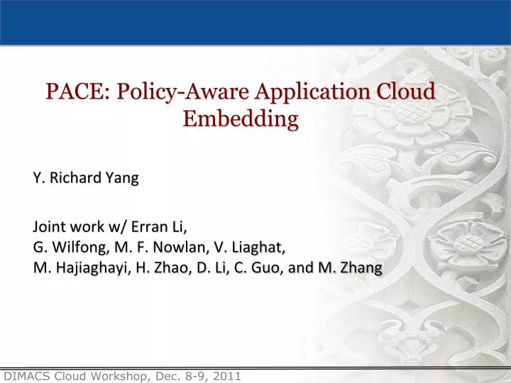
PACE: Policy-Aware Application Cloud Embedding. Y. Richard Yang Joint work w/ Erran Li, G. Wilfong , M. F. Nowlan , V. Liaghat , M. Hajiaghayi , H. Zhao, D. Li, C. Guo , and M. Zhang. Motivation. App. On-demand. Cloud. Data Center 1. Data Center 2. VM. VM. LUN. VM. VM.

E N D
PACE: Policy-Aware Application Cloud Embedding Y. Richard Yang Joint work w/ Erran Li, G. Wilfong,M. F. Nowlan, V. Liaghat, M. Hajiaghayi, H. Zhao, D. Li,C. Guo, and M. Zhang
Motivation App On-demand Cloud Data Center 1 DataCenter 2 VM VM LUN VM VM VM LUN LUN LUN A key aspect of cloud computing is on-demand allocation of infrastructure resources to construct applications
Example Real App Internet CE F2 F1 (Firewall) S2 S1 R1 LB2 LB1 (Load balancer) IPS2 IPS3 IPS1(Intrusion prevention) S6 S4 S5 S3 tier-1 VLAN 100 VLAN 200 Logger VLAN 300 VLAN 400 Tier-2 Tier-1 Tier-3
App Structure Properties • A real-world application is nota set of isolated resources (e.g., VMs/LUNs) • Real world-applications are constructed with external entities (e.g., policy boxes) to enhance functionality, • 95% web applications have severe vulnerabilities if deployed alone [WASC]
Policy-Aware Application Cloud Embedding • What is it? • Construct structured applications, according to application policies, in cloud settings
Why Worry about PACE? Internet CE F2 F1 (Firewall) S1 S2 LB2 LB1 (Load balancer) IPS2 IPS1(Intrusion prevention) S4 S3 tier-1 VLAN 300 VLAN 400 Tier-2 Tier-1 • Example 1: Relocating tier-1 servers in VLAN 300 and 400 to cloud • Issues • IPS1 is used to monitor cross VLAN traffic. After relocation, cross traffic will not be monitored by IPS1 • Tier-1 servers cannot reach tier-2 servers
Path2 u’3 v’3 VLAN 200 VLAN 100 Why Worry about PACE? Data Center 2 Data Center 1 L2 Extension Link R1 Path1 IPS3 S7 S5 S6 u3 v3 VLAN 100 VLAN 200 • Example 2: Extending VLAN 200 and 100
PACE Key Components App App App Policy API Infrastructure Orchestrator App/Cloud Stat Provisioning System
Policy Specification: Flow Policy Graph • For each application, introduce Flow Policy Graph (FPG) as a compact, abstract representation of its embedding policy • A FPG consists of • Nodes: equivalent application-level entities • Edges: QoS/reliability demand and distributed information flow control (DIFC) policy for traffic between nodes • Focus on DIFC requirements
Example: Nodes Internet CE F2 F1 (Firewall) S1 S2 R1 LB2 LB1 (Load balancer) IPS2 IPS3 IPS1 (Intrusion prevention) S6 S4 S5 S3 tier-1 VLAN 500 VLAN 100 VLAN 200 Logger VLAN 300 VLAN 400 Tier-2 Tier-1 Tier-3
Example: FPG Nodes LB1 Ex LB2 T3-V200 T3-V100 T1-V400 T2-V500 T1-V300
Distributed Information Flow Control • Graph based information flow control (IFC) representation • Default “off” policy: no inter-node communications • Edge DIFC annotation indicates required declassifier(s) to allow inter-node communication • Declassifiers may be either hardware or software appliances
FPG: IFC Declassifier • A declassifier is identified by its function class, instance configuration, and optional a name, e.g., • F: a firewall pipedeclassifier • IPS: an IPS pipedeclassifier • LOG: a replicationdeclassifier • A declassifier can have internal state • Two declassifiers with the same name is a single instance
Edge Direction and Multiple DIFC Declassifiers • Edges are directional: the two directions of traffic between two nodes can have different DIFC policies • We call each direction a link • By default, assume that two links of the same edge have the same DIFC policy • Multiple DIFC declassifiersmay be specified on the same link • The semantics is ordered execution
Example: Annotating FPG with DIFC F/acl1;f1 LB1 Ex LB2 F/acl1;f1 T3-V200 T3-V100 T1-V400 T2-V500 T1-V300
Example: Annotating FPG with DIFC LB1 Ex LB2 F1 ips1, log1 F2 ips1, log1 ips1,log1 ips1, log1 F2 T3-V200 T3-V100 T1-V400 T2-V500 T1-V300 Same instancerequired forcorrelation ips1, log1
Example: Annotating FPG with DIFC LB1 Ex LB2 F1 ips1, log1 F2 ips1, log1 ips1,log1 ips1, log1 F2 ips1,log1 ≠ log1, ips1 T3-V200 T3-V100 T1-V400 T2-V500 T1-V300 ips1, log1
Example: Annotating FPG with DIFC LB1 Ex LB2 F1 ips1, log1 F2 ips1, log1 ips2 ips1,log1 ips1, log1 F2 Same ACL used on 4 edges. Does the app really want it? T3-V200 T3-V100 T1-V400 T2-V500 T1-V300 ips2,F2 ips3 ips1, log1 ips2,F2 ips3
From FPG to Cloud Embedding • Given • A network N; • Applications and their policies represented by FPGs • Determine • Forwarding in the network and/or • Allocation of resources to satisfy FPGs.
From FPG to Cloud Embedding • Embedding depends on multiple factors • New app vs migration/extension • Declassifier deployment locations • In-network devices (e.g., correlating/learning IPS) • End devices (hypervisors) • Network forwarding mechanisms • Traditional spanning tree, flow table, flow table w/ encapsulation, L2/L3 tunnels, PSwitch
Why is Embedding (Theoretically) Hard? • A Special Embedding Problem: the k-paths-tree problem: • An application with K+1 nodes • a root R and • a set of source nodes (VMs) S = {s1, s2, . . . , sK} already deployed • A set of distinct policy function instances M = {x1, x2, . . . , xK}, whose locations in the network are already deployed • Policy: Each edge i, 1 ≤ i≤ K, si -> R needs delcassifierxi
NP-Reduction • If tree-based forwarding, it is NP-hard to determine feasibility of embedding. • We reduce the NP-complete problem k-node-disjoint-path problem to our problem • Given an instance of k-node-disjoint path problem, we compute an instance of our policy embedding problem
NP-Reduction t1 t2 tK G s1 s2 sK
NP-Reduction R x1 x2 xK t1 t2 tK G NP-hardness still holds even if DC is fat-tree. s1 s2 sK
Flow-Table Forwarding Embedding LB1 Ex LB2 F1 ips1, log1 F2 ips1, log1 ips2 ips1,log1 ips1, log1 F2 T3-V200 T3-V100 T1-V400 T2-V500 T1-V300 ips2,F2 ips3 ips1, log1 ips2,F2 ips3 • Assume app entities and declassifiers’ locations at the network are given, what is the condition to make flow-table forwarding only enforcementpossible?
Embedding w/ Flow Table Forwarding x1, x2, …, xK As Ad There exist paths p0, ... pK, where path piis from xito xi+1, such that • No policy conflict: Each piis conflict free, i.e., it does not traverse a declassifer that conflicts with the given x1to xK. • No forwarding conflict: If a switch x belongs (not tail) to multiple paths in {p0, … pK}, then the incoming ports are distinct among these multiple paths. Consider each app edge As→ Ad with x1,x2, ..., xK For notation, let As == x0, Ad == xK+1
Example: Feasible ips, log LB1 T1 log, ips LB1 T1 1 2 s1 3 1 s2 2 3 ips log
Example: Infeasible ips, log LB1 T1 LB1 log 1 2 s1 3 path(LB1→ ips) and path(log → T1) forwarding conflict on switch 2/port 1 ips 1 2 s2 3 1 s3 T1
Handling Forwarding Infeasibility If infeasibility is due to forwarding conflict, and L2 encapsulation is allowed, add next-hop MAC to resolve forwarding conflict.
Placement of App and Declassifiers Orchestrator ✔ • Placement • App entities (VMs) and • declassifiers Forwarding to enforce PFG Previous Proposition assumes that placement of app and declassifiers is given. What if we have placement flexibility?
Placement: Cloud Setting • A physical cloud network G(V, E) • Each physical node v in the cloud has capacity: • Function C : V → N: C(v) is # of VMs that it can host • Function Fx: V → N: Fx(v) is # of contexts of declassifier type x that it can host. • Each physical link has bandwidth: • Function B : E → N: B(e) is amount of available bw
Placement: Batch Embedding • For each cloud location pair a→ b, compute M paths: R1(a →b), …, RM(a → b) • For each cloud location pair a →b and sequence of declassifiersx1,x2, ..., xK, compute set of feasible flow-table forwarding paths Pa → b • Hence each app with a FPG can be served by picking one feasible flow-table forwarding path for each of its FPG links • Need to refactor FPG to extract shared declassifiers
Placement: Batch Embedding • A batch set R of app requests to be handled • Let p be a feasible embedding of app request r • yrp: indicator {0, 1} variable of using p to satisfy r
Online Embedding based on Dual • Comment • Gives a B-competitive fractional embedding • use rounding to convert to actual embedding • A negative result: no o(|R|)-comp. online embedding
Simplification: Extension/Migration Embedding LB2 Ex LB1 F1 ips1, log1 F2 ips1, log1 ips2 ips1,log1 ips1, log1 F2 T3-V200 T3-V100 T1-V400 T2-V500 T1-V300 ips2,F2 ips3 ips1, log1 ips2,F2 ips3 • Policy-aware embedding can be simpler if • policy has been enforced in an original network and • cloud (public/private data centers) is used for extension/migration
Setting • Assume each app entity is enforced as a VLAN in original network Cloud Private/Public Center Original Network VLAN y VLAN x Migrate or copy as template
Solution: PACE Proxy • Introduce Sproxy and Vtarget Cloud Private/Public Center Original Network vtarget L2 tunnel Sproxy VLAN y VLAN x VLAN y VLAN x Migrate or copy as template
Solution: PACE Proxy • Link each serving switch of each migrated/extension template to Sproxy in original w/ VLAN label Cloud Private/Public Center Original Network vtarget Sproxy VLAN x VLAN y VLAN y VLAN x VLAN y VLAN x Migrate or copy as template
Solution: PACE Proxy • Configure forwarding tables of Sproxy and Vtarget to enforce policies back at original network Cloud Private/Public Center Original Network vtarget Sproxy VLAN x VLAN y VLAN y VLAN x VLAN y VLAN x Migrate or copy as template Encapsulation using QinQor MACinMAC
Summary • Cloud deployment faces policy-aware embedding issues • Introduce Flow Policy Graph as a DIFC based approach to capture policies • Future work: integrated label based DIFC • Cloud embedding efficiency depends on • Network forwarding mechanisms (flow table is promising) • Placement algorithms (competitive fractional alg. But worst case can be bad) • Extension/migration can provide simpler solutions for embedding • Introduced the proxy approach for enforcing at original • May also compute mirrors to enforce at both
Preliminary Evaluations A campus network 50 routers and 1000 switches Policies inferred based on topology properties and route distribution graph Scope of a policy If both endpoints are in the same VLAN, the scope is all nodes in the broadcast domain of the VLAN If endpoints are in different VLAN, the scope is all nodes reachable (based on route distribution graph and ACLs) within the security zone Scope is extended to include relevant nodes in remote data center
Evaluation (Cont’d) Policy violation without PACE BGP redistributions routes to remote data center into base networks three types of communication: UU sessions (among relocated servers) UL2domain (between relocated and those remaining at the same L2 domain) UExternal (between relocated and those outside the campus network).
Evaluation (Cont’d) Overhead of policy enforcement
Evaluation (Cont’d) • Setup for algorithm evaluation • Three typical data center structures Bcube, Dcell, and fat-tree • Bcube: 2187 leaf nodes and 4 levels of 3-port mini-switches • Each switch has 150 middlebox instances • Each leaf node has 300 VMs • Each link has a bandwidth of 1Gbps • Dcell(32,1): 1056 leaf nodes • Each leaf node has 500 VMs • each switch has 1000 middlebox instances • each link has bandwidth 1Gbps • Fat-tree with k = 24: 3456 leaf nodes; three middlebox placements: (I) aggregation switch, (II) half aggregation, half access (III) access switch • Application request: average number of VM and middleboxes is 50 and 60, average bandwidth is 350Mbps
Evaluation (Cont’d) • Comparison of online fractional algorithm with integral one
Path2 v’1 u’1 Why Worry about PACE? • Problem when end hosts communicate directly in remote: • a simple example when topology mismatch Remote Data Center Path1 S4 S1 IPS3 IPS1 IPS2 S5 S3 S2 v1 u1
Existing policy preservation techniques: Virtualization layer support: Vmware introduces Virtual Service Domain (VSD) which allows a group of VMs to be protected by virtual appliances Switch support: data center switch supports port policy migration with attached VM, e.g. Voltaire switch However, for performance and availability of functionality, some policies must be enforced in network Existing Work
Feasibility and Optimality Depends on routing and policy enforcement mechanisms available in the base network and remote network Feasibility: Key factors in the design space affecting feasibility policies Where to enforce At base At remote Both base and remote Connection/remote capabilities Remote is spanning-tree: determine feasibility is NP-hard Pswitch, and Openflow L2 or L3 tunnels: feasible by constructing two primitives---Mosaic Proxy, Mosaic Mirror Optimality: objectives and constraints depends on deployment scenarios Objectives: Minimizes total path length Minimizes cost: cost of network extension includes VM rental cost, Internet cost, middlebox cost Constraints: application performance constraints including bandwidth, delay, jitter