Download
1 / 25
250 likes | 251 Views
Computer Networks Al-Mustansiryah University Elec. Eng. Department College of Engineering Fourth Year Class. Lec 5 Layers. 2-3 LAYERS IN THE OSI MODEL. In this section we briefly describe the functions of each layer in the OSI model.

E N D
Computer Networks • Al-Mustansiryah University • Elec. Eng. DepartmentCollege of Engineering Fourth Year Class Lec 5 Layers
2-3 LAYERS IN THE OSI MODEL In this section we briefly describe the functions of each layer in the OSI model. OSI Layers: Application Layer Presentation Layer Session Layer Transport Layer Network Layer Data Link Layer Physical Layer
Note • The application layer is responsible for providing services to the user. • Examples: • Email • Web browsers • Protocol Data Unit (PDU) - User Data The application layer is also concerned with the following 1) Network virtual terminal. 2) File transfer. 3) Mail services. 4) Directory services.
Note • The presentation layer is responsible for translation, compression, Code Formatting and encryption. • PDU - Formatted Data The Presentation layer is also concerned with the following 1) Translation. 2) Encryption. 3) Compression.
Note • The session layer is responsible for dialog control and synchronization. • PDU - Formatted Data The Session layer is also concerned with the following 1) Dialog control. 2) Synchronization.
Note • The transport layer is responsible for the delivery of a message from one process to another. • PDU - Segments The Transport layer is also concerned with the following • 1) Service-point addressing. • 2) Segmentation and reassembly. • 3) Connection control. • 4) Flow control. • 5) Error control.
Figure 2.11 Reliable process-to-process delivery of a message
Note • The network layer is responsible for the delivery of individual packets from the source host to the destination host. • PDU – Packets The Network layer is also concerned with the following 1) Logical addressing. 2) Routing.
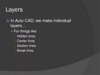
The data link layer is responsible for moving frames from one hop (node) to the next. • PDU - Frames The data link layer is also concerned with the following • 1) Framing. • 2) Physical addressing. • 3) Flow control. • 4) Error control. • 5) Access control.
The physical layer is responsible for movements of individual bits from one hop (node) to the next. • PDU - Bits The physical layer is also concerned with the following • 1) Physical characteristics of interfaces and medium. • 2) Representation of bits. • 3) Data rate. • 4) Synchronization of bits. • 5) Line configuration. • 6) Physical topology. • 7)Transmission mode.
Data Flow and Encapsulation • Data flow occurs when two devices are connected in a network with some kind of shared transmission medium. • An application running on the source device creates some kind of data. This happens at the Application layer. • The application needs to add encryption to that data. This will be done at the Presentation layer. • At the Session layer it appends the Session ID. • The Transport layer breaks the data into blocks of data which we call Segments . Every Segment also gets the Port number to identify which upper layer application needs to receive the data on the destination device • The Network layer takes the Segment, and appends the source and destination IP address. At that point the Segment becomes a Packet. • At Data Link layer the source and destination MAC address and the CRC is added. At this point we have a Frame. • The Frame then is sent to the physical device where it is translated into some kind of a signal (often call it Bits)
Decapsulation at the Destination Device • The destination device receives series of bits and interprets them as a Frame. • It removes MAC addresses and the CRC, and passes the data up to the Network layer. • IP addresses are removed and the Packet is forwarded up to the Transport layer . • The Port number is looked at and the Segment gets forwarded up the to the appropriate application specified by the Port number. • The Session ID is used. • Encryption will be removed. • The data in its original form is presented to the application that needs to interpret it.
2-4 TCP/IP PROTOCOL SUITE The original TCP/IP protocol suite was defined as having four layers: host-to-network, internet, transport, and application. However, when TCP/IP is compared to OSI, we can say that the TCP/IP protocol suite is made of five layers: physical, data link, network, transport, and application.