Download

1 / 25
250 likes | 460 Views
PSPICE 计算机仿真. Simulation Program with Integrated Circuit Emphasis. CH6. INDUCTORS, CAPACITORS, AND NATURAL RESPONSE 电感、电容和零输入响应. You should know,. Resistor The value of resistance (In ohms) Inductor (initial current) The value of inductance (In henries) Capacitor (initial voltage)

E N D
PSPICE计算机仿真 Simulation Program with Integrated Circuit Emphasis
CH6 INDUCTORS, CAPACITORS, AND NATURAL RESPONSE 电感、电容和零输入响应
You should know, • Resistor • The value of resistance (In ohms) • Inductor (initial current) • The value of inductance (In henries) • Capacitor (initial voltage) • The value of capacitance (In farads)
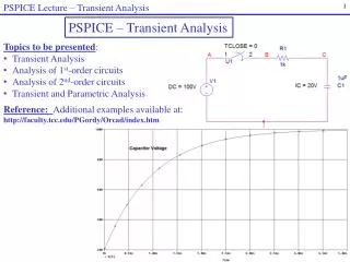
6.1 Transient Analysis (暂态分析) • You use transient analysis to examine the response of a circuit as a function of time.
You may examine the output of a transient analysis in two different ways. • First, you may direct PSpice to write the results of transient analysis to the output file. • Second, you may use Probe to generate plots of voltage and current versus time.
6.2 Natural Response • To find the natural response of a circuit, you first find the initial inductor currents and capacitor voltages.
Example 10 illustrates how to use PSpice to find the natural response of a series RLC circuit. We incorporated a preliminary analytic solution as part of the example to permit checking the validity of the PSpice solution.
Example 10 • a) analyze the natural response of the circuit shown in Fig. 65 with respect to the type of damping, the peak value of Vc, and the frequency of oscillation.
b) Use PSpice to analyze the circuit’s natural response. Then use Proble to generate a plot of the voltage Vc versus t, and use the Proble cursor to identify the peak value of the voltage.
Solution a) • For the series circuit shown in Fig. 65,
Hence the response is underdamped(欠阻尼), and the roots of the characteristic equation are:
Based on the solution for Vc, the peak value of Vc is 7.70 V, and it occurs at t=362.69 µs. The damped frequency(衰件频率) is 7000 rad/s, and thus the damped period(衰减周期) is 897.60 µs.
Solution b) • To get the signs right, you must pay attention to the orientation of these parts. (Fig. 66) • The initial voltage is positive at the left-most terminal of the capacitor, or bottom terminal if the part is rotated once. • The initial current enters the left-most terminal of the inductor, or terminal of the inductor, or bottom terminal if the part is rotated once.
Set the initial values(设定初值) • The initial capacitor voltage is 10 V. • The initial inductor current is -90 mA. • These values are set in the Property Editor, in the column labeled IC. (Fig. 66a)
Trace/Cursor/Display • 显示坐标 • Trace/Cursor/Peak • 显示峰值
Result • We see from the cursor output window that the peak output voltage is 7.7347 V (书上:7.7255 V), which occurs at t=371.222 us (书上:372.181 us), which is in good agreement with our analytic results in (a).