Download
1 / 64
640 likes | 654 Views
Object Oriented Analysis and Design in Software Development. State University of Campinas UNICAMP - Brazil. Ricardo Gudwin. Developing using UML: The main Phases. Requirements Specification Proposing a problem Analysis Investigation of the problem Design Logical Solution Construction

E N D
Object Oriented Analysis and Design in Software Development State University of Campinas UNICAMP - Brazil Ricardo Gudwin
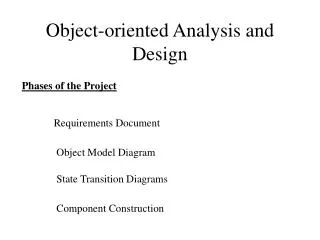
Developing using UML:The main Phases • Requirements Specification • Proposing a problem • Analysis • Investigation of the problem • Design • Logical Solution • Construction • Building code
Requirements Specification Phase State University of Campinas UNICAMP - Brazil Ricardo Gudwin
Developing using UML:Requirements Specification • Requirements - description of needs or desires for a product • Primary goal - identify and document what is really needed in the system • Challenge - define requirements unambiguously • First Steps • Understand and Characterize the Problem • Propose how can a software system solve the problem • Main Result - Requirements Specification Report
Requirements Specification Report • Document with the following chapters • Problem Comprehension - verbal description of the domain problem • Software solution proposal - verbal description proposing how a software system can be envisioned to solve the problem • assertion of goals • Logistic Plan • Working Teams - people involved in the project • Affected Groups - groups affected by the current project • Assumptions - things assumed to be true • Risks - things which can lead to failure or delay - potential consequences of failure or delay • Dependencies - other parties, systems and products that the project depends upon for completion
Requirements Specification Report • List of System Functions • what a system is supposed to do • List of System Attributes • what a system is supposed to be • List of Use Cases • Narrative of possible interactions between the users (including external users - other systems) and the system • Use Case Diagrams • UML diagram for capturing use cases • Glossary of Terms • List of main terms being used to describe system functions, attributes and use cases
Problem Comprehension • Examples: • 1-) We want to build a new electronic product (e.g. a cellular phone), with a full set of features (e.g. fast dialing, mnemonic memory, emergency dialing, embedded pager, etc). • 2-) We have a large set of data (customers, suppliers, products, parts, etc), and want to find a good way to organize, access and update all this information. • 3-) We have a process that we want to model and analyze in order to make predictions of its behavior and test the impact of different decisions on the results we are going to obtain. • 4-) We have a business, with all its logistics and methods, and want to improve its efficiency, reliability and cost-effectiveness. • 5-) We want to produce some sort of goods in an efficient, reliable and automatic way, using automatic machines.
Software Solution Proposal • Examples: • 1-) Use of microprocessors or micro-controllers within the product, with an embedded software to provide the desired features • 2-) Use of a database system to manage the data. • 3-) Development of a simulator to simulate the process and provide the statistics for decision analysis • 4-) Use of productivity tools (e.g. office tools, e-mail, web-sites), and special purpose software applications in order to automate parts of the business process. • 5-) Development of a control system software in order to control the machines involved in good productions.
List of System Functions • Example: Cellular Phone System Software
List of System Attributes • Example: Cellular Phone System Software
Use Case • Use Case: Dial Phone Number • Actors: User • Purpose: Describe the process of dialing a number • Overview: The User informs the device he wants to dial a phone number, enter a sequence of 1 to n digits, informs the system he ended entering the number and the system start dialing • Type: Primary and essential • Cross Reference: Functions F1.1 Attributes A1.3
Types of Use Cases • Primary, Secondary and Optional • Primary: represent major common processes - e.g. Dial Phone Number • Secondary: represent minor or rare processes - e.g. Program Number in Memory • Optional: processes that may not be tackled - e.g. Get Program Version Number • Essential versus Real • Essential: are expressed in an ideal form that remains relatively free of technology and implementation details • Real: concretely describes the process in terms of its real current design, committed to specific input and output technologies and so on (NOT USED IN REQUIREMENTS PHASE)
Use Case Diagram User Program Number in Memory Delete Number in Memory <<extends>> <<extends>> Search Memory Dial Confidential Phone Number Dial Number in Memory Dial Phone Number Check Password <<include>> Validate User Voice Validation
Requirement Analysis Phase State University of Campinas UNICAMP - Brazil Ricardo Gudwin
Developing using UML:Analysis • Requirement Analysis: employing a deep investigation and enhancement of requirement specifications • Objectives • Complement description of essential Use Cases • Identify concepts in order to create an initial Conceptual Model • Detail processes, creating an initial Behavioral Model • Main challenge: maintain an abstract level of investigation, without entering within design questions • Main result: • Requirement Analysis Report
Requirement Analysis Report • Document with the following chapters • Analysis Summary: describing how the analysis steps were performed (sequence of activities), and the main artifacts to appear • Initial Conceptual Model: capture the main concepts used in specifications, and start defining the terminology used to describe the future system components • Conceptual Class Diagram • Initial Behavioral Model: details the description of use cases given in specifications, preparing the room for design • Sequence Diagrams • Contracts
Building a Conceptual Model • Conceptual Model: • illustrates meaningful concepts in a problem domain - the things we should be aware of • it is the most important artifact to create during object-oriented analysis • represents real-world things, NOT software components • Contents: • Concepts • Associations between concepts • Attributes of concepts
Building a Conceptual Model • Concept: • informally- an idea, thing or object; • formally - defined by its symbol, intension and extension • symbol - words or images representing a concept • intension - the definition of a concept • extension - the set of examples to which the concept applies • Structured Analysis x Object-Oriented Analysis • Structured Analysis focus on processes or functions • Object Oriented Analysis focus on concepts • Strategy to Identify Concepts • Searching the Use Cases description overview • Speculating on additional related concepts
Building a Conceptual Model • Concept Category List: • physical or tangible objects • specifications, designs or descriptions of things • places • transactions • transaction line items • roles of people • containers of other things • things in a container • other computer or system external to our system • Abstract noun concepts • organizations • events • processes (often not represented as a concept) • rules and policies • catalogs • records or finance, work, contracts, legal matters • financial instruments and services • manual, books
Building a Conceptual Model • Conceptual Modeling Guidelines • List the candidate concepts using the noun phrase identification and the Concept Category List • Draw them in a Conceptual Class Diagram • Add the associations necessary to record relationships • Add the attributes necessary to fulfill information requirements • Avoiding Irrelevant features • use names of things that do exist; exclude irrelevant features; do not add things that are not there • Concepts or Attributes ? • If we do not think of some concept X as a number or a text in the real world, X is probably a concept, not an attribute • If in doubt, make it a separate concept
Building a Conceptual Model • Specification or Description Concepts: • abstract concepts used to specificate or describe other concepts • When are they needed ? Add a specification or description concept when: • deleting instances of things they describe (e.g. Item) results in a loss of information that needs to be maintained, due to the incorrect association of information with the deleted thing • it reduces redundant or duplicated information • Examples: • Product, ProductSpecification • Item, ItemDescription
Conceptual ModelAdding Associations • Association: relationship between concepts that indicates some meaningful and interesting connection • Criteria for useful Associations: • Associations for which knowledge of the relationship needs to be preserved for some duration (need-to-know associations) • Associations derived from the Common Associations List
A is a physical part of B A is a logical part of B A is physically contained in/on B A is logically contained in B A is a description for B A is a line item of a transaction or report B A is known/logged/recorded/ reported/captured in B A is a member of B A is an organizational sub-unit of B A uses or manages B A communicates with B A is related to a transaction B A is a transaction related to another transaction B A is next to B A is owned by B Common Associations List
Conceptual ModelAdding Associations • How Detailed Should Associations Be ? • Common pitfall: spend too much time during investigation trying to discover associations • Finding concepts is much more important than finding associations. Spend more time in finding concepts than finding associations • Association Guidelines • Too many associations tend to confuse a conceptual model rather than to illuminate it. Their discovery can be time-consuming with marginal benefit • Avoid showing redundant or derivable associations • Declare association names, roles and multiplicity only when necessary
Conceptual ModelAdding Attributes • Attribute: logical data value of an object • It is necessary to identify those attributes of concepts that are needed to satisfy the information requirements of the current use cases under development • Conceptual Model: representation of real world things, not software components - attributes for read things. • Attributes to include: • those for which the requirements suggest or imply a need to remember information • Valid Attribute Types: • Boolean, Date, Number, String, Time, Color, Geometrics (Point, Rectangle, …), etc.
Conceptual ModelAdding Attributes • Attributes generally are Pure Data Values: • those for which unique identity is not meaningful • e.g. separate instances of the Number 5, of the String ‘start’,etc. • Modeling Attribute Quantities and Units • use a separate concept “unit” associated to given amounts • Avoid Foreign Keys: current values of attributes of associated concepts
Building a Behavioral ModelSystem Sequence Diagrams • System Behavior: what a system does, NOT how it does it • Behavioral Model: • System Sequence Diagrams: for each Use Case in specifications, there should be ONE OR MORE sequence diagram. Multiple sequence diagrams are used to illustrate different courses of action on a same scenario. • Contracts: for each message appearing within an earlier sequence diagram, there should be a contract ruling it. • Sequence of Actions: • Use Cases -> Sequence Diagrams -> Contracts
Example of a System Sequence Diagram • Use Case: DialPhoneNumber :System : User 1: ServiceRequest(DialingRequest) 2: enterItem(Digit) Repeat until complete Phone Number 3: Dial()
Behavioral ModelContracts • Contracts: • describe the effect of operations upon the system, in terms of what a system’s state changes are when the operations are invoked. • describes WHAT a system does, without explaining HOW it does it. • For each operation appearing in a system sequence diagram, there should be a corresponding contract • Contract Sessions • The contract is divided into sections. • Each section provides information about a specific part of the contract
Contracts • Name • name of operation, and parameters • Responsibilities • An informal description of the responsibilities this operation must fulfill • Type • Name of type (concept, software class, interface) • Cross References: • System function reference numbers, use cases, etc. • Notes • Design notes, algorithms, and so on.
Contract • Exceptions • Exceptional cases • Output • Non-UI (User Interface) outputs, such as messages or records that are sent outside of the system • Pre-Conditions • Assumptions about the state of the system before execution of the operation • Post-Conditions • The state of the system after completion of the operation
Contracts • How to Make a Contract • Identify the system operations from the system sequence diagrams • For each system operation, construct a contract • Start by writing the Responsibilities section, informally describing the purpose of the operation • Then complete the Post-conditions section, declaratively describing the state changes that occur to objects in the conceptual model • To describe the post-conditions, use the following categories • Instance creation and deletion • Attribute modification • Associations formed and broken
Contracts • Notes: • The Post-Conditions are the most important part of a contract • Do not confuse Outputs with Post-Conditions • Post-conditions are not actions to be performed during the operation, but declarations about the system state after the operation is performed • Post-conditions are related to the conceptual model • what instances can be created ? Those from the conceptual model • what associations can be formed ? Those in the conceptual model • During the creation of contracts, it is normal to discover the need for new concepts, attributes or associations not within the conceptual model. These should be included into the conceptual model.
Contracts • How Complete Should Post-conditions be ? • Generating a complete and accurate set of post-conditions for a system operation is not likely - or even necessary - during the analysis phase • Fine details will be discovered during the design phase. • Pre-conditions • define assumptions about the state of the system required before the operation is performed • Examples • Things that are important to test at some point of the operation • Things that will not be tested, but upon which the success of the operation hinges - important because document them to future readers of the contract, highlighting their importance in future phases.
Contracts • Advice on Writing Contracts • After filling in the operation name, fill in the Responsibilities section first, Post-conditions section next, Pre-conditions last. • If a developer finds no use in filling a particular section, it’s OK. • Use the Notes section to discuss any design details, such as algorithms or the high-level sequential steps • Use the Exceptions section to discuss the reaction to exceptional situations • State the post-conditions in a declarative, passive tense form (was …) to emphasize the declaration of a state change rather than of an action. • Don’t forget to include the forming of associations when new instances are created
Example of Contract • Name : ServiceRequest(service) • Responsibilities: Send a service request to the system • Type: concept • Cross References: UC: DialPhoneNumber, F1.1 • Notes: (none) • Exceptions: Dialer not available • Output: • Pre-Conditions:System is on-line, Dialer not busy • Post-Conditions: • System is aware of the desired service • The right server to provide the service is created • The server is initialized to start the service
Design Phase State University of Campinas UNICAMP - Brazil Ricardo Gudwin
Developing using UMLDesign • Analysis Phase: emphasizes an understanding of the requirements, concepts and operations related to a system - WHAT are the processes, concepts, etc. • Design Phase: starts the development of a logical solution based upon object-oriented paradigm - HOW are the processes, concepts, etc. implemented • Basic Issues: • architectural design • development of real use-cases • creation of interaction diagrams • assigning responsibilities • design patterns
Developing using UMLDesign • Software Systems • Monolythic Applications • Multi-Threaded Applications • Client-Server Systems • Component Based Systems
Developing using UMLDesign • Three-Tier Architecture • User Interface • Application Logic • Storage Process Data Collect Data Generate Statistics
Developing using UMLArchitectural Design • Multi-Tiered Object-Oriented Architectures • includes the separation of responsibilities • Decomposing the Application Logic Tier into finer layers • Domain concepts • Services • A logical three-tier architecture may be physically deployed in various configurations. • Example 1 (Fat Client) • User Interface + Application Logic -> Client computer • Storage -> Server computer
Developing using UMLArchitectural Design • Example 2 (Fat Server) • User Interface -> Client computer • Application Logic + Storage -> Server computer • Example 3 (Distributed system) • User Interface -> Client computer • Application Logic -> Distributed over multiple server computers • Storage -> Distributed over multiple server computers • Logical solution: Package diagrams • Physical solution: Deployment diagrams
Developing using UMLArchitectural Design • Package Diagram • packages can be hierarchically nested • each package comprises a domain of functionally related classes and objects • packages can be developed within a design cycle or re-utilized from existing components
Developing using UMLArchitectural Design • Deployment Diagram • At this point, the physical solution is envisioned, in order to evaluate how different parts of the system are going to be developed • The configuration may change during design
Developing using UMLDesign Main Trail • After the primary definition of an architecture • Real Use Cases • Design Class Diagram • Interaction Diagram • The above diagrams are designed interactively: • From essential use-cases derived in the Analysis phase, we develop now Real Use Cases, where aspects regarding User Interface and Storage are explicitly considered. • As soon as we define each real use case, we use the information within it to feed the Design Class Diagrams. • Design Class Diagrams are distributed within the packages showed at the Package Diagram
Developing using UMLDesign Main Trail • Instances of objects from classes on the Design Class Diagrams have their interaction described through Interaction Diagrams: • Collaboration Diagrams (mainly) • Sequence Diagrams (in some cases) • The assignment of responsibilities in order to create the objects and classes implementing the real use cases, that are represented by interaction diagrams, may be due the use of GRASP Design Patterns (General Responsibility Assignment Software Patterns) • The messages appearing in each interaction diagram are further regulated by means of software contracts. • Detailed description of real use cases may require the use of State diagrams and/or Activity diagrams
Developing using UMLDesign Main Trail • Notes: • Design Class Diagrams are not a simple evolution of Conceptual Class diagrams. There should be some resemblance between them, but Design Class Diagrams can be potentially different from Conceptual Class diagrams developed in analysis phase. • Main differences will be due to the inclusion of objects for creating and managing the user interface and storage. • The development of real use cases include the design of the windows comprising the user interface • The conceptual object “System” appearing in System Sequence Diagrams will now be replaced by the creation of new objects that will interact with the user and with each other.
Name:NamedInstance Class :Instance 3.3:WaitCall 3.1: create 1: StartApplication :Kernel :Listener 2: create : User 3.2: start 1*: [I=1..15] dig:=getValue():value 4.1: create 4.2: start :Dialer :Digit :Dialer Developing using UMLCollaboration Diagrams • Example of Collaboration Diagrams