Download
1 / 45
540 likes | 1.13k Views
Lecture 16 : (17/11/09). Reaching and Grasping. Reference Frames Configuration space Reaching Grasping. Michael Herrmann. michael.herrmann@ed.ac.uk, phone: 0131 6 517177, Informatics Forum 1.42. Prehension. Goal: Understand ideal robot mechanisms for

E N D
Lecture 16: (17/11/09) Reaching and Grasping Reference Frames Configuration space Reaching Grasping Michael Herrmann michael.herrmann@ed.ac.uk, phone: 0131 6 517177, Informatics Forum 1.42
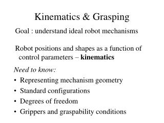
Prehension Goal: Understand ideal robot mechanisms for reaching, grasping and manipulation Robot positions and configurations as a function of control parameters – kinematics Need to know: • Representing mechanism geometry • Standard configurations • Degrees of freedom • Grippers and graspability conditions
3D Coordinate Systems Left handed (Right handed reverses the +Z direction)
Vectors & Points in 3D Point Vector
Local Reference Frames can be expressed as • Local (translated) coordinates • Global (untranslated) coordinates Local frame could also have further sub-local frames
Translations Move to :
A lot of conventions Here: q positive is anti-clockwise when looking along +Z • in local (rotated) coordinates is (a,b,c)T’ • in global (unrotated) coordinates is (a cos(q)-b sin(q), a sin(q)+b cos(q),c)T Rotations Rotate about Z axis
Rotation Matrix Representation I Much more compact and clearer!
Other Rotation Representations All equivalent but different parameters: • Yaw, pitch, roll • Azimuth, elevation, twist • Axis + angle • Slant, tilt, twist • Quaternions roll pitch yaw
Full Rotation Specification • Need 3 angles for arbitrary 3D rotation • Lock & key example • Rotation angles : • Warning: rotation order by convention but must be used consistently:
Full Transformation Specification Each connection has a new local coordinate system Need to specify 6 degrees of freedom = 3 rotation + 3 translation
Kinematic Chains is at: In C2: In C1: In C0:
Homogeneous Coordinates I Messy when more than 2 links, as in robot So: pack rotation and translation into Homogeneous coordinate matrix Extend points with a 1 from 3-vector to 4-vector Extend vectors with a 0 from 3-vector to 4-vector Pack rotation and translation into 4x4 matrix: 3 rotation parameters: 3 translation parameters:
Homogeneous matrices scaling translation projection perspective 0 rotations view plane z=0, center of projection at (0,0,-d)
Homogeneous coordinates II In C2: In C1: In C0: Longer chains for robot arms (e.g. 6 links):
Degrees of Freedom Controllable DoF: number of joints Effective DoF: number of DoF you can get after multiple motions A car has 2 controllable (move, turn), but can adjust (x,y) position and orientation, so 3 effective DoF Task DoF: Configurations in space dimensionality: 2D : 3 (x, y, angle) 3D : 6 (x, y, z, 3 angles)
Joint geometry Linear (prismatic) joint: slides parametrize one translation direction per joint e.g. Sliding in the x direction Hinge (revolute) joint: rotates parametrize one rotation angle per joint e.g. Rotation about x-axis trf(q,0,0,0,0,0) trf(0,0,0,l,0,0) l
Configuration Space I Alternative representation to scene coordinates Number of joints = J J-dimensional space Binary encoding: 0 for invalid pose, 1 for free space Real-valued encoding: “distance” from goal configuration Point in C.S. = configuration in real space Curve in C.S. = motion path in real space
A B Dynamics: Trajectory Planning What is the shortest path in configuration space? At what speed the path is traversed? Cost to go (energy or wear) Time to goal Least perturbations (predictability) Maximal smoothness Minimal intervention
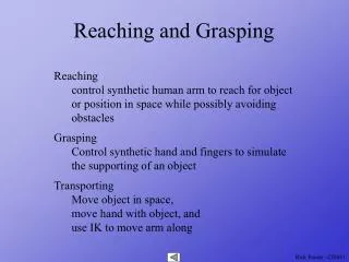
Forward and Inverse Kinematics Forward: Given joint angles, find gripper position Easy for sequential joints in robot arm: just multiply matrices Inverse: Given desired gripper position, find joint angles Hard for sequential joints – geometric reasoning
Sequential & Parallel Mechanisms Simplified into 2D Serial manipulator Parallel manipulator vary: vary:
Equilibrium point hypothesis A. G. Feldman 66 Bizzi et al. 78 Gribble et al. 98 • Extensors: rubrospinal tract • Flexors: pontine reticulospinal tract • Force-field experiments: violation of equifinality at variations of velocity-dependent load (Hinder & Milner 03) Solution: Internal dynamics models (Shadmehr & Mussa-Ivaldi 94)
Specifying Robot Positions • Actuator level: specify voltages that generaterequired joint angles. • Joint level: specify joint angles and let systemcalculate voltages. • Effector level: specify tool position and letsystem compute joint angles. • Task level: specify the required task and let thesystem compute the sequence of tool positions Most robot programming is at levels 2 and 3.
Grippers and Grasping Gripper: special tool for general part manipulation Fingers/gripper: 2, 4, 5 Joints/finger: 1, 2, 3 Your hand: 4 fingers * 4 DoF + thumb * 5 DoF+ wrist * 6 DoF = 27 DoF (22 controllable DoF).
Barret Hand 2 parallel fingers (spread uniformly) 1 opposable finger DoF: 4 fingers (2 finger joints bend uniformly)
Finger Contact Geometry Coefficient of friction at fingertip: Surface normal: Direction perpendicular to surface: Friction cone: Angles within about surface normal Force direction: direction in whichfinger pushed No-slip condition:
Force Closure Need balanced forces or else object twists 2 fingers – forces oppose: 3 fingers – forces meet at point: Force closure: point where forces meet lies within 3 friction cones otherwise object slips
Other Grasping Criteria Some heuristics for a good grasp: • Contact points form nearly equilateral triangle • Contact points make a big triangle • Force focus point near CoM
Grasp Algorithm • Isolate boundary • Locate large enough smooth graspable sections • Compute surface normals • Pick triples of grasp points • Evaluate for closure & select by heuristics • Evaluate for reachability and collisions • Compute force directions and amount • Plan approach and finger closing strategy • Contact surface & apply grasping force • Lift (& hope)
Kinematics Summary • Need vector & matrix form for robot geometry • Geometry of joints & joint parameters • Forward & inverse kinematics • Degrees of freedom • Grippers & grasping conditions
Classical Control Paradigm: “SPA” SPA lacks SPA is serial ad hoc analytical assumptious speed and efficiency modularity and scalability flexibility and adaptivity error-tolerance and robustness
Quotations by R. Brooks”fast, cheap, and out of control” • Planning is just a way of avoiding figuring out what to do next. • The world is its own best model • Complex behavior need not necessarily be the product of a complex control system • Simplicity is a virtue • Robots should be cheap • All on-board computation is important • Systems should be build incrementally • Intelligence is in the eye of the observer • No representation, no calibration, no complex computers
Objections that can be misleading • In a different environment the robot will fail. [a function that deals with this problem may reduce robustness] • The system cannot be debugged [bugs, too, are in the eye of the observer] • It’s not scalable! [“Elephants don’t play chess”]
Subsumption Architecture Evaluation of progress if not Scheduling of subtasks if not (sub-) Goal approach if not Path planning if not Self-localization & -calibration if not Obstacle avoidance if not Move when clear act sense
Evaluation of the Subsumption Architecture • “I wouldn’t want one to be my chauffeur” (C. Torpe) • Modifications at low-levels affect higher levels • Often there the hierarchy is not strict • Priorities rather than inhibition • Representations, plans, and models do help • Reproducibility is a virtue • SPA is top-down, SubsArc is bottom-up • “neats vs. scruffies”
Modular architectures • Schemas (M. Arbib) • Circuit architecture: Situated automata (L. Kaelbling) • Action selection (P. Maes), behavior-based robotics (R. Arkin) • Dynamical systems and ant colonies • Cognitive architectures
Deliberator Sequencer Controller Three-layer architecture (TLA) Erann Gat, 1998 Planning, search, reasoning standard programming Competition, scheduling, and adaptation of behaviours Elementary behaviours
Architectures Summary • Simplicity is a virtue • The subsumption architecture is simple and extendable and usually good to start with 3. The ultimate goal is to interface reasoning with the real world 4. Limited resources, noise and complexity are problems in any approach to robot control