Download
1 / 56
560 likes | 580 Views
STRUCTURAL ANALYSIS : load flow. external forces (actions) : gravitational pull of the earth on the mass of the structure, its contents and the things that move through it. thrust from retained earth or water. pressure and suction of wind.

E N D
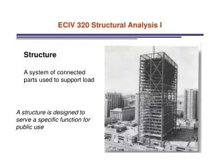
STRUCTURAL ANALYSIS : load flow
external forces (actions) : gravitational pull of the earth on themass of the structure, its contents and the things that move through it. thrust from retained earth or water. pressure and suction of wind. inertial force due to earthquakes (ground acceleration). impact from explosions or flying objects support settlement
GRAVITY LOADS. dead load (DL) permanent self-weight including structure, enclosure, finishes and appendages. live load (LL) transitory loads based upon use and occupancy including people, cars and furniture. snow load (S) semi-permanent load based on local snowfall statistics. snow load may have a lateral component.
area loads account for loads which are spread out uniformly over an area. line loads account for loads which occur along a line which may be uniform or vary. point loads are discrete forces which occur at a specific location.
tuned mass damping Behavior of this damper during the 2005 Szechuan earthquake: https://www.youtube.com/watch?v=NYSgd1XSZXc Taipei 101 Building in Taiwan. Completed 2003-2004. Overall height 509 m (1671 ft). 728-ton counterweight ball hung at 87th/88th floor
Recall the method of solving for reactions when you have a point load: 200 lb ( + ) SM1 = 0 -200 lb(10 ft)+ RY2(15 ft) = 0 RY2(15 ft) = 2000 lb-ft RY2 = 133 lb ( +) SFY = 0 RY1 + RY2 - 200 lb = 0 RY1 + 133 lb- 200 lb = 0 RY1 = 67 lb ( +) SFX = 0 RX1 = 0 RX1 10 ft 5 ft RY2 RY1 200 lb 0 lb 10 ft 5 ft 67 lb 133 lb
Now what if you have a uniformly distributed load? w = 2000 lb/ft RX1 RY1 RY2 20 ft
resultant force - equivalent total load that is a result of a distributed line load resultant force = “area” of loading diagram resultant force = w( L) RX1 RY1 RY2 20 ft
resultant force - equivalent total load that is a result of a distributed line load resultant force = area of loading diagram resultant force = w( L) = 2000 lb/ft(20ft) = 40,000 lb RX1 10 ft 10 ft RY1 RY2 20 ft * This resultant force is located at the centroid of the distributed load.
resultant force - equivalent total load that is a result of a distributed line load resultant force = area loading diagram resultant force = w( L) = 2000 lb/ft(20ft) = 40,000 lb RX1 10 ft 10 ft RY1 RY2 20 ft ( + ) SM1 = 0
resultant force - equivalent total load that is a result of a distributed line load resultant force = area loading diagram resultant force = w( L) = 2000 lb/ft(20ft) = 40,000 lb RX1 10 ft 10 ft RY1 RY2 20 ft ( + ) SM1 = 0 -40,000 lb(10 ft)+ RY2(20 ft) = 0
resultant force - equivalent total load that is a result of a distributed line load resultant force = area loading diagram resultant force = w( L) = 2000 lb/ft(20ft) = 40,000 lb RX1 10 ft 10 ft RY1 RY2 20 ft ( + ) SM1 = 0 -40,000 lb(10 ft)+ RY2(20 ft) = 0 RY2(20 ft) = 400,000 lb-ft
resultant force - equivalent total load that is a result of a distributed line load resultant force = area loading diagram resultant force = w( L) = 2000 lb/ft(20ft) = 40,000 lb RX1 10 ft 10 ft RY1 RY2 20 ft ( + ) SM1 = 0 -40,000 lb(10 ft)+ RY2(20 ft) = 0 RY2(20 ft) = 400,000 lb-ft RY2 = 20,000 lb
resultant force - equivalent total load that is a result of a distributed line load resultant force = area loading diagram resultant force = w( L) = 2000 lb/ft(20ft) = 40,000 lb RX1 10 ft 10 ft RY1 RY2 20 ft ( + ) SM1 = 0 -40,000 lb(10 ft)+ RY2(20 ft) = 0 RY2(20 ft) = 400,000 lb-ft RY2 = 20,000 lb ( + ) SFY = 0
resultant force - equivalent total load that is a result of a distributed line load resultant force = area loading diagram resultant force = w( L) = 2000 lb/ft(20ft) = 40,000 lb RX1 10 ft 10 ft RY1 RY2 20 ft ( + ) SM1 = 0 -40,000 lb(10 ft)+ RY2(20 ft) = 0 RY2(20 ft) = 400,000 lb-ft RY2 = 20,000 lb ( + ) SFY = 0 RY1 - 40,000 lb + RY2 = 0
resultant force - equivalent total load that is a result of a distributed line load resultant force = area loading diagram resultant force = w( L) = 2000 lb/ft(20ft) = 40,000 lb RX1 10 ft 10 ft RY1 RY2 20 ft ( + ) SM1 = 0 -40,000 lb(10 ft)+ RY2(20 ft) = 0 RY2(20 ft) = 400,000 lb-ft RY2 = 20,000 lb ( +) SFY = 0 RY1 - 40,000 lb + RY2 = 0 RY1 - 40,000 lb + 20,000 lb= 0
resultant force - equivalent total load that is a result of a distributed line load resultant force = area loading diagram resultant force = w( L) = 2000 lb/ft(20ft) = 40,000 lb RX1 10 ft 10 ft RY1 RY2 20 ft ( + ) SM1 = 0 -40,000 lb(10 ft)+ RY2(20 ft) = 0 RY2(20 ft) = 400,000 lb-ft RY2 = 20,000 lb ( + ) SFY = 0 RY1 - 40,000 lb + RY2 = 0 RY1 - 40,000 lb + 20,000 lb= 0 RY1 = 20,000 lb
resultant force - equivalent total load that is a result of a distributed line load resultant force = area loading diagram resultant force = w( L) = 2000 lb/ft(20ft) = 40,000 lb RX1 10 ft 10 ft RY1 RY2 20 ft ( + ) SM1 = 0 -40,000 lb(10 ft)+ RY2(20 ft) = 0 RY2(20 ft) = 400,000 lb-ft RY2 = 20,000 lb ( +) SFY = 0 RY1 - 40,000 lb + RY2 = 0 RY1 - 40,000 lb + 20,000 lb= 0 RY1 = 20,000 lb ( +) SFX = 0 RX1 = 0
resultant force - equivalent total load that is a result of a distributed line load resultant force = area loading diagram resultant force = w( L) = 2000 lb/ft(20ft) = 40,000 lb RX1 10 ft 10 ft RY1 RY2 20 ft ( + ) SM1 = 0 40,000 lb(10 ft)- RY2(20 ft) = 0 RY2(20 ft) = 400,000 lb-ft RY2 = 20,000 lb ( +) SFY = 0 RY1 + RY2 - 40,000 lb = 0 RY1 + 20,000 lb- 40,000 lb = 0 RY1 = 20,000 lb ( +) SFX = 0 RX1 = 0 w = 2000 lb/ft 0 lb 20 ft 20,000 lb 20,000 lb
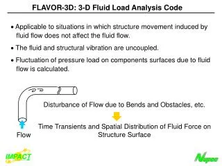
framing diagram plan vertical load flow : deck > beam > girder > column
UNIFORM LOAD SPAN 1/2 LOAD 1/2 LOAD
LENGTH Tributary Width is the width of area that contributes load to a specific spanning element. assumed distributed line load from deck: Area Load = DL+LL w = (Trib Width) (Area Load) w BEAM
Tributary Area is the area that contributes load to a specific structural element. PBEAM = (Trib Area BEAM) (Area Load) PBM PBM PBM
Tributary Area to the column includes loads from the girders and beams which frame directly to the columns PCOL = (Trib Area) (Area Load) PCOL
retainingheight (H) 1/3 H lateral earth pressure(30-120 lb/ft3)(H) earth pressure load
Wind Load is an ‘Area Load’ (measured in PSF) which loads the surface area of a structure.
Wind Loading W2 = 30 PSF W1 = 20 PSF
Wind Load spans to each level 1/2 LOAD W2 = 30 PSF SPAN 10 ft 1/2 + 1/2 LOAD SPAN 10 ft W1 = 20 PSF 1/2 LOAD
Total Wind Load to roof level wroof= (30 PSF)(5 FT) = 150 PLF
Total Wind Load to second floor level wsecond= (30 PSF)(5 FT) + (20 PSF)(5 FT) = 250 PLF
wroof= 150 PLF wsecond= 250 PLF
Seismic Load is generated by the inertia of the mass of the structure : VBASE Redistributed (based on relative height and weight) to each level as a ‘Point Load’ at the center of mass of the structure or element in question : FX VBASE wx hx S(w h) VBASE = (Cs)(W) ( VBASE ) Fx = https://www.youtube.com/watch?v=snfcsLuLY88
Total Seismic Loading : VBASE = 0.3 W W = Wroof + Wsecond