Download
1 / 28
290 likes | 300 Views
Chapter 11: Stereopsis. Stereopsis : Fusing the pictures taken by two cameras and exploiting the difference (or disparity) between them to obtain the depth information of the scene. ○ Stereo imaging. (1) Bring the first camera to coincide with the world

E N D
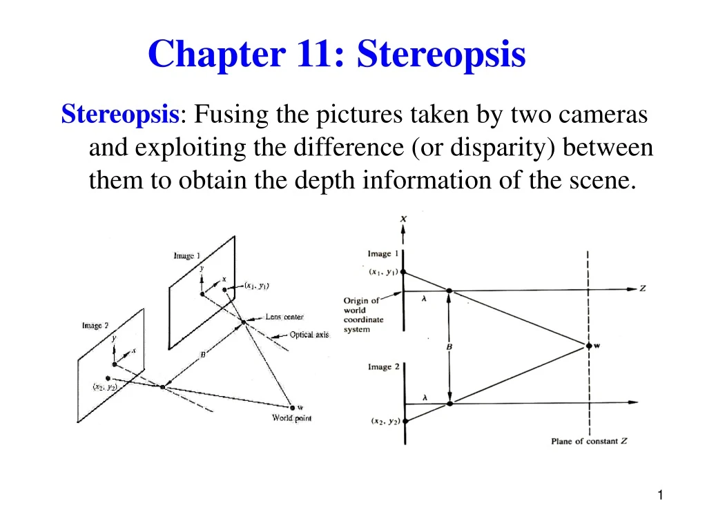
Chapter 11:Stereopsis Stereopsis: Fusing the pictures taken by two cameras and exploiting the difference (or disparity) between them to obtain the depth information of the scene.
○ Stereo imaging (1) Bring the first camera to coincide with the world coordinate system. The coordinates of w Similarly, (2) (3) Substitute (2) into (1) (4) Solve for Z
11.1.1 Image Rectification -- Replace the input images with pictures parallel to the baseline
Idea: Make the rectified epipolar lines lie on the scanline, which is paralleled to the baseline
11.1 3D Reconstruction -- Recover 3D information from 2D data ○ Stereo vision involves: Feature extraction Feature correspondence Depth estimation 3D shape reconstruction 。Epipolar constraint restricts feature correspondence along epipolar lines
○ Difficulties: 。 Sparse depth information
。 Measurement errors: The rays R and R’ will never intersect due to calibration and feature localization ( p and p’) errors
○ Solutions: 。Heuristic approach (1) Find the line segment perpendicular to R and R’ (2) Take its mid-point P as the preimage of p and p’
。Algebraic approach: Given (a) projection matrices: M and M’ (b) matching points: p and p’ From perspective projection relations, i) This is an over-constrained system of four (2 for p and 2 for p’) independent linear equations in P (3 unknowns x, y, z) ii) Solve using linear least-squares techniques.
。Optimization method: Reconstruct the scene point Q by where p, p’: discrete pixels q , q’: actual images Solve using nonlinear least-squares techniques
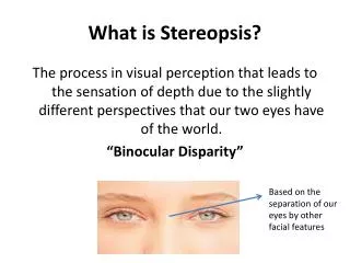
11.3 Binocular Fusion ○ Random dot stereogram -- A pair of images obtained by randomly spraying black dots on a small square plate floating over a larger one
Stereoscopically, the image pair gives the impression of a square in front of the surround
。Cooperative stereopsis algorithm (Marr and Poggio, 1976) -- relies on three constraints: (a)Compatibility -- Two image features can only match if they possess similar properties (b) Uniqueness -- A feature in one image matches at most one feature in the other picture (c) Continuity -- The disparity of matches varies smoothly in the image
11.3.1 Correlation -- Find pixel correspondences by comparing intensity profiles in the neighborhood of potential matches
○ Problem of assuming that the observed surface is (locally) parallel to the two image planes • Two-pass algorithm: • Use initial estimates • of the disparity to • warp the windows • to compensate for • unequal amount of • foreshortening ii) Find disparity and its derivatives that maximize the correlation between the two windows
11.3.2 Multi-Scale Edge Matching -- Edge matching preferred to point matching -- Correspondences are found at a variety of scales
○ Multi-scale binocular fusion algorithm 。 Larger scale -> fewer noises, less precise in location 。Smaller scale -> more noises, more precise in location
superimposition Image 2 Image 1 Single scale matching Multiscale matching
11.3.3 Dynamic Programming ○ Ordering constraint In case 1, the order of feature points along the two epipolar lines is the same. In case 2, a small object lies in front of a larger one. Some surface points are not visible in one of the images (e.g., A is not visible in the right image), and the order of the image points (e.g., B and D) is not the same in the two pictures. Case 2 Case 1
○ Example: Match intervals between two corresponding epipolar lines
11.4 More Cameras 11.4.1 Three Cameras -- Additional cameras eliminate ambiguity ○ The third image can be used to check hypothetical matches between the first two pictures i) A 3D point is first constructed from two images and is then projected onto the third image ii) Given three cameras and two images of a point, predict its position in a third image by intersecting corresponding epipolar lines
11.4.2 Multiple Cameras ○ Multicamera method (Okutami and Kanade 1993) Matches are found using all pictures.