Download
1 / 31
310 likes | 316 Views
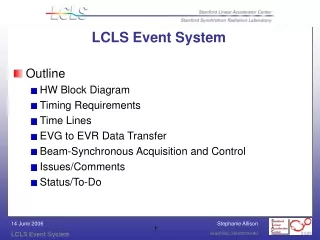
LCLS CAVITY BPM SYSTEM DESIGN. LCLS Cavity BPM Overview. RF BPM system current status Planning for prototype testing Planning for 8 LTU BPMs electrically identical to those in the undulator. Planning for 33 undulator BPMs. LTU and Undulator BPM System Specification.

E N D
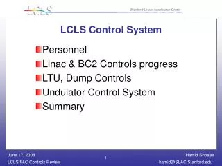
LCLS Cavity BPM Overview • RF BPM system current status • Planning for prototype testing • Planning for 8 LTU BPMs electrically identical to those in the undulator. • Planning for 33 undulator BPMs
X-Band Cavity BPM Design • SLAC selective coupling design • Solid Copper Body • WR-75 waveguide output • Waveguide transition brazed to body
Dipole Cavity Design • Beam pipe radius = 5 mm • Cavity radius = 14.937 mm • Cavity gap = 3 mm • Distance beam axis to bottom of wg = 9.5 mm • Waveguide= 19.05 x 3 mm
Port 1 Port 4 Port 2 Port 3 H-field Produced by 0.4 mm Horizontal Offset • Waveguides are magnetically coupled to the cavity fields. • Waveguide coupling is symmetric in each plane. • Cross-talk contribution from the nonzero horizontal component of the hfield at ports 2 and 4 couples into waveguide. • Cross-talk can likely be improved by reducing waveguide coupling and by reducing the waveguide height. Courtesy G. Waldschmidt
Monopole Cavity Design • Beam pipe radius = 5 mm • Cavity radius = 11.738 mm • Cavity gap = 2 mm • Coupling Slot = 4 x 2 mm • Shortest distance from cavity opening to bottom of waveguide=1.734 mm • Waveguide= 19.05 x 3 mm
Survey and Alignment • Cylindrical design aids survey and CMM alignment • Cylindrical design for ease of machining • Solid Copper Body • Alignment surface flats for mounting
Cold Test Prototype • Non-vacuum cold test prototype • Removable end caps • Accelerates test fixture development and cold test procedures • Prototype end of Nov. 05
Miteq X-Band Low Noise Receiver • Existing product line • WR 75 Waveguide Interface • Low Noise Figure (2.7 dB) • Prototype delivery date 12/10/05 • Budgetary price for prototype $6500.00
PDRO local oscillator • 11.424 GHz (119 MHz x 96) • Phase lock to 119 MHz ref 0 dBm +/- 3 dB • +13 dBm output power • In-Band Spurs <70 dBc • Phase noise depends on 119 MHz reference
Noise Estimates • Sensitivity: -58 dBm/0.2nC/1m • Minimum bit size: 16 bits/micron@ 0.2nC • Assumes 2 gain ranges for 75 dB • Noise floor <200 nm rms
Long Lead Item Status • Receiver Prototype del. 12/10/05 • Local oscillator del. 11/24/05 • Waveguide del. 12/1/05 • Waveguide calibration kit del. 12/9/05 • CPI Vacuum windows 11/30/05
APS Test Objectives • Develop a cavity BPM that meets system requirements and can be manufactured economically • Develop simulation model that correlates to prototype data • Transition from prototyping to production
Phase I Injector Test Stand ITS Install single X-Band Cavity and modified off-the-shelf down converter receiver Mount BPM on Piezo two-axis translation stage Phase II Bypass line test with PC gun Install three X-Band Cavities BPMs Bypass line test with PC gun to start June 06 BPM System Test Approach
Injector Test Stand ITS Beam Parameters • Charge- 1 nC single-bunch • Bunch length- ~ 3 - 4 ps FWHM for ps laser • Spot size on final screen at 5.5 MeV ~ 0.75 mm rms, ps laser
Phase I Data Acquisition Design Approach • Instrument three channel down converters with Struck SIS-3301-105 ADCs 14-bit • Single VME board will provide the data acquisition for 8 channels • Epics driver complete • Digitize horizontal, vertical position and Intensity 0 to 1 volt range • Fit Data to decaying exponential at 60 MHz
Phase I Testing Objectives • Test prototype Cavity BPM, down converter, and data acquisition • Generate preliminary compliance table to specification • Gain operational experience to determine if translation stage is useful, what are optimum operating parameters
Phase I Schedule Milestones • Design and develop prototype Cavity BPM • Prototype non vacuum • Nov 05 • Build single Cavity BPM • Dec 05 • Cold Test • Dec 05 • Install cavity BPM into ITS and Test • Jan 06
Phase II Schedule Milestones • Refine design and develop First Article Cavity BPM and support hardware • Jan 06 • Build 3 Cavity BPMs • Mar 06 • Cold Test • May 06 • Install cavity BPM into APS PAR/Booster bypass line and Test • June 06
Phase II Testing Objectives • First Article Prototypes evaluated • Test three BPM separated by fixed TBD distance to determine single-shot • Complete test matrix
LTU and Undulator Planning • Receiver and LO housed in shielded enclosure below girder 20 watt power dissipation maximum • Presently BPM output on wall side • BPM output flexible waveguide section allows movement for alignment
BPM Mounting • BPM connects directly to the girder. • Mechanical translation stage used for alignment • BPM and Quad can move independently with respect to each other
Cost Savings • Reduce the dipole cavity outputs from 4 ports to 2 ports • Terminate the unused ports in vacuum • Eliminate 2 transitions, 2 windows, waveguide, 2 magic tees • Prove resolution and offset performance