Download
1 / 16
160 likes | 345 Views
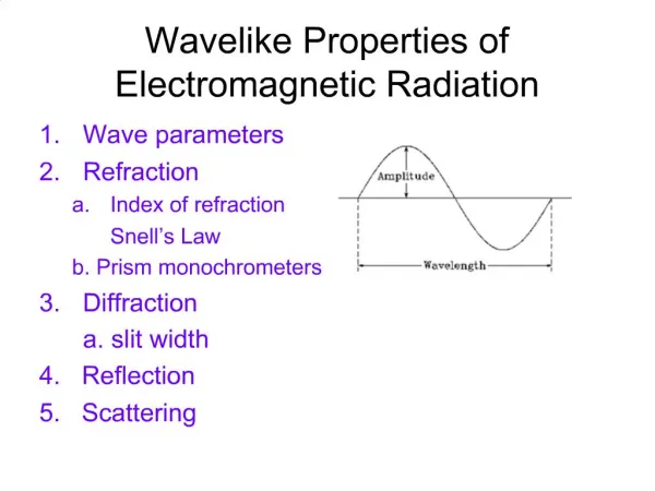
The Study of Elastic Properties with the Use of Electromagnetic Acoustic Transducers (EMAT). Sanjiv Goli. Outline. Objectives & motivation The physics of EMAT Experimental setup Data/Analysis Final Remarks. Objective & Motivation.

E N D
The Study of Elastic Properties with the Use of Electromagnetic Acoustic Transducers (EMAT) Sanjiv Goli
Outline • Objectives & motivation • The physics of EMAT • Experimental setup • Data/Analysis • Final Remarks
Objective & Motivation • Use EMAT to observe the transmission of ultrasound through materials (metals) with the goal of studying the materials’ elasticity • To investigate elastic properties of materials, with one purpose being industrial application • EMAT technique is very recent (a decade)=> desire to participate in and contribute to a new type of research
A material falls into one of two classifications, based on structure of the material’s atoms Isotropic Anisotropic Anisotropy requires measurement of the elasticity along different spatial axes Project: four electrically conductive isotropic materials (a brass cylinder, a brass plate, aluminum, and stainless steel) Experimental Materials (Diagram at http://www.webelements.com/webelements/compounds/media/Na/Cl1Na1-7647145.jpg, date accessed 6/29/05)
EMAT Design • EMAT (Electromagnetic Acoustic Transducers) • Transducers: coils vs. piezoelectric crystals • Coils placed on both sides of material (but no direct contact with material, especially since material is conductive) • Pulse-Echo technique: stimulated by pulse generator, a high freq alternating current is produced in one coil
The Creation of Ultrasound • Creates eddy currents on the surface of the material • F = IdlxB => Lorentz force acts on eddies, causing molecules of the material to vibrate, and ultrasonic waves are created; ultrasound, because freq > 20 kHz • Ultrasound propagates back & forth across material • Some acoustic energy is converted back into electrical energy at the second coil, which is detected by an oscilloscope (Photo taken from: Physics 201: Using the Oscilloscope and a Study of the Fast RC Circuit. 28 July 2005 <http://www.bradley.edu/las/phy/academics/laboratories/201lab2004/fast_rc/fastrc.pdf>.)
Ultrasonic vibrations are mathematically associated with elasticity Isotropic: CL = pVL2 CT = pVT2 Studied transverse waves Ultrasound, continued • V = 2L / t, if t is time between echoes
The First EMAT • Dimensions of transducer: 5 mm coil on a 10 x 10 mm square using .2 mm diameter copper wire thread through .2 mm diameter holes = eyestrain • Tried hand-made as well as machine-cut coils • First attempt at getting a significantsignal failed
Second Experimental setup • Most likely reason is that impedances of pulse generator and the EMAT were very different • Matching the impedances would allow for a stronger, amplified signal • No impedance-matching due to time constraints • Probe with machine-cut coils at its tip, between which a material could be placed
Success! • We observed a signal on 4 different samples, some signals stronger than others • For several different field strengths (up to 31 T), time between peaks was used to calculate ultrasonic velocity • Also measured amplitude decay during pulse propagation (Brass Plate, 26 Tesla)
Example: Brass Plate @ 31 T • Amplitude decreases exponentially • Attenuation: • α = -20*k in units of dB/μs, where k is slope of graph • Here, attenuation is 2.572 dB/μs
Further Observation & Analysis • Calculated velocities in all 4 samples in fields up to 31 T • Aluminum: from 3.1268227x105 cm/sec ± 5.049343x103 cm/sec • to 3.1804348x105 cm/sec ± 5.454721x103 cm/sec • Unfortunately, could not calculate values for attenuation on two of the samples due to insufficient data (brass cylinder) (brass plate)
Amplitude vs. Field Strength • Investigated how the amplitude of specific peaks depends on magnetic field strength • Theory gives that F = IdlxB. In agreement with theory, the following was observed: • Data displays linearity • R2 coefficient strong (.995) • (Stainless Steel)
Final Remarks • Again, experiment strongly supports that amplitude of ultrasonic signal varies linearly with magnetic field • These velocities can be used to calculate elastic constants for samples • Impedance-matching might have resulted in a better signal (the high field strength overrode the unmatched impedances problem)
Acknowledgements • Many thanks to the following people and groups: • Alexei Souslov • Gina LaFrazza • CIRL, REU program • National Science Foundation
Citations • “EMATS for Science and Industry”, Hirao & Ogi, 2003 • http://www.webelements.com/webelements/compounds/media/Na/Cl1Na1-7647145.jpg, date accessed 6/29/05 • Physics 201: Using the Oscilloscope and a Study of the Fast RC Circuit. 28 July 2005 http://www.bradley.edu/las/phy/academics/laboratories/201lab2004/fast_rc/fastrc.pdf.