Download
1 / 56
590 likes | 716 Views
steering system of ships

E N D
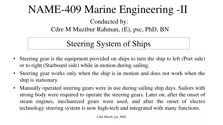
NAME-409 Marine Engineering -II Conducted by: Cdre M Muzibur Rahman, (E), psc, PhD, BN Steering System of Ships • Steering gear is the equipment provided on ships to turn the ship to left (Port side) or to right (Starboard side) while in motion during sailing. • Steering gear works only when the ship is in motion and does not work when the ship is stationary. • Manually operated steering gears were in use during sailing ship days. Sailors with strong body were required to operate the steering gears. Later on, after the onset of steam engines, mechanized gears were used, and after the onset of electro technology steering system is now high-tech and integrated with many functions. Cdre Muzib, psc, PhD
Basic requirements for steering gears guided by IACS rules can be briefly outlined as: The steering gear should be capable of steering the ship from 35 degrees port to 35 degrees starboard and vice-versa with the vessel plying forwards at a steady head-on speed for maximum continuous rated shaft rpm and summer load waterline within a time frame of maximum 28 seconds. It is to be power operated where necessary to meet the above conditions, and where the stock diameter exceeds 120 mm. With one of the power units inoperative, the rudder shall be capable of turning 15 degrees port to 15 degrees starboard (and vice-versa) within a time frame of 1 minute with the vessel moving at half its rated maximum speed or 7 knots (whichever is greater) at summer load line. The major power units and the control systems are to be duplicated so that if one of them fails, the other can easily substitute for them as standby. The steering system is to be provided with additional power unit (hydraulic pump etc.) connected to the emergency power supply from Emergency Generator, which shall be capable of turning the rudder from 15 degrees from one side to other side within 60 seconds with the vessel moving at a maximum service speed or 7 knots, whichever is greater. • • • • • Cdre Muzib, psc, PhD
Steering system of ships Steering gear systems categories: • Mechanical • Steam-mechanical • Electro-mechanical • Hydraulic • Pneumatic –hydraulic • Electro-hydraulic • Jet steering Complete Steering Gear system consists of three main parts, namely: • Telemotor (Transmitter and receiver system) • Control Unit • Power Unit Cdre Muzib, psc, PhD
Steering system of ships • Transmitter is located on the navigation bridge/wheel house, which transmits the given order to the Receiver located in the steering gear compartment, by turning the steering wheel or joystick or feeding autopilot data. The wheel order may be transmitted to the Receiver through mechanical, pneumatic, hydraulic or electric signals. • The Receiver conveys this order to the Control Unit, also located in the steering gear compartment. • The control unit signal is then magnified/amplified in the power unit to execute rudder stock motion towards port or starboard through mechanical, electric or hydraulic power. • Floating gear and hunting gear are part of control system but they are for feed back arrangement about rudder position. Floating lever gets activated by the movement of the transmitter plunger. Hunting lever is used to center-up the steering pump or to bring the pump in non-pumping position as and when rudder has reached the desired angle. Cdre Muzib, psc, PhD
When the steering wheel 1 is turned anticlockwise, the pinion 2 moves the toothed rack 3 downward and moves the toothed rack 4 upward. As it is fixed to the two piston 5 and 6, the piston also moves correspondingly. As these two cylinders 7 & 8 are filled with oil, the movement of the pistons result in oil pressure being applied to the bottom of the piston 10 and moves it upward and these forces the oil in upper part of cylinder 9 up in to the cylinder 8. Piston 10 has a piston rod connected to a slide valve 11. In its middle position, the slide valve just closes the ports 12, 13, 14 in the slide valve housing 15. As the piston 10 moves upward, the slide valve 11 also moves along with it and opens port 12 and 14. These cause oil from the pressure vessel to come under side of the piston 20 and the oil above piston 20 is forced in to the slide valve housing 15 and out through the port 12 to the discharge tank 16. As a result the piston 21 moves upward along with the piston 20 since both these piston are connected together by piston rod. These upward movements of the two pistons impart movement to the tiller arm which is mounted on the rudder stock and hence moves the rudder. Cdre Muzib, psc, PhD
Rotary vane steering gear – Rotary vane steering gear is usually fitted with 3 fixed vanes and 3 moving vanes and can turn to 700of total rudder movement i.e 350on each side. Cdre Muzib, psc, PhD
Rotary vane steering gear Cdre Muzib, psc, PhD
* Rotor C is fitted and keyed to a tapered rudder stock A, stator B is secured to the ship’s structure. Fixed vanes, secured equidistantly in the stator bore and rotating vanes secured equidistantly in the rotor, form two sets of pressure chambers in the annular space between the rotor and stator. * They are interconnected by a manifold. Fluid supplied at pressure to one set of these chambers will rotate C clockwise and the rudder will turn to port, or to starboard if the alternate set is put under pressure. * The fixed and rotating vanes may be of spheroidal graphite cast iron. They are securely fixed to the cast steel rotor and stator by high tensile steel dowel pins and cap screws. Keys are also fitted along the length of the rotary vanes, for mechanical strength. * Assembly of the gear would not be possible if the fixed vanes were keyed; they rely on the dowels to provide equivalent strength. The vanes fixing is considered to be of sufficient strength to make them suitable to act as rudder stops. Steel sealing strips, backed by synthetic rubber, are fitted in grooves along the working faces of the fixed and rotary vanes, thus ensuring a high volumetric efficiency, of 96—98% even at the relief valve pressure of 100 bar or over. Rotation of B is prevented by means of two anchor brackets, and two anchor pins. The anchor brackets are securely bolted to the ship. * Vertical clearance is arranged between the inside of the stator flanges and the top and bottom of the anchor brackets to allow for vertical movement of the rudderstock. This clearance varies with each size of the rotary vane unit, but is approximately 38 mm in total and it is necessary that the rudder carrier should be capable of restricting the vertical movements of the rudderstock to less than this amount. Cdre Muzib, psc, PhD
Ram Steering System Single Ram Cdre Muzib, psc, PhD
Double RAM Double ram unit: two rams are working simultaneously so that the force of two diagonally opposite rams can act on the tiller as couple to produce double the turning effect. Double ram unit can be of two cylinder or four cylinder Cdre Muzib, psc, PhD
Four Ram Twin Rudders Cdre Muzib, psc, PhD
Hydraulic System of Steering Cdre Muzib, psc, PhD
Hydraulic Pump of Steering Steering pumps are basically of two major types: Radial piston type (Hele-Shaw) Axial Piston type (Swash plate) Variable Stroke Radial Piston Pump (Hele Shaw Pump) Cdre Muzib, psc, PhD
Variable Stroke Radial Piston Pump (Hele Shaw Pump) Movement of the floating rings from mid position displaces the circular path of rotation of the piston from that of the cylinder block and pumping action. produces a Cdre Muzib, psc, PhD
Variable Stroke Radial Piston Pump (Hele Shaw Pump) Cdre Muzib, psc, PhD Fig 9.4 [HD McGeorge, p 291]
The pump (Figure 9.4a) consists of case A, to which are attached two covers, the shaft cover B and the pipe connection cover C. This latter cover carries the D tube (or central valve), which has ports E and F forming the connections between the cylinders and branches G and H. The cylinder body J is driven by shaft K, and revolves on the D tube, being supported at either end by ball bearings T. The pistons L are fitted in radial cylinders, and through the outer end of each piston there is a gudgeon pin M, which attaches the slippers N to the piston. The slippers are free to oscillate on their gudgeon pins and fit into tracks in the circular floating ring O. This ring is free to rotate, being mounted on ball bearings P, which are housed in guide blocks R. The latter bear on tracks formed on the covers B and C and are controlled by spindles S, which pass through the pump case A. The maximum pump stroke is restricted by the guide block ends coming in contact with the casing. Further restriction of the pump stroke is effected externally. Figure 9.4b shows sections through the D tube, cylinder body, pistons and slippers at right angles to the axis. XY is the line along which stroke variations take place. The arrow indicates the direction of rotation. With the floating ring central, i.e. concentric with the D tube, (1) the slippers move round in a circle concentric with the D tube, and consequently no pumping action takes place. With the floating ring moved to the left, (2) the slippers rotate in a path eccentric the D tube and cylinders, consequently the pistons, as they pass above the line XY, recede from the D tube and draw oil through the ports, E, whilst the pistons below XY approach the D tube and discharge oil through ports F. With the floating ring moved to the right (3) the reverse action takes place the lower pistons moving outwards drawing oil through ports F and the upper pistons moving into the cylinders and discharging oil through ports E. The direction of flow depends on the location of the floating ring, left or right of the centre. The floating ring can be moved to any intermediate position between the central and maximum positions; the quantity of oil discharged varies according to the amount of displacement of the floating ring from its mid-position. Cdre Muzib, psc, PhD
Variable Stroke Axial Piston Pump (swash plate pump) The driving shaft rotates the cylinder, barrel, swash plate and piston. An external enables the swash plate to be moved about its axis which varies the stroke of the piston in the barrel. turning Cdre Muzib, psc, PhD
Figure 8.18 Variable Stroke Axial Piston Pump [Smith, p 280] A. Input shaft B. Tilting box C. Roller bearings D. Connecting rod E. Piston F. Cylinder barrel G. Relief valve H. Replenishing valve J. Ports K. Valve plate L. Barrel joint M. Universal joint N. Socket ring O. Control trunnion P. Control cylinder Cdre Muzib, psc, PhD
Swash-plate axial-cylinder pump A circular cylinder barrel is bored and splined centrally to suit the input shaft with which it revolves. Several cylinder bores are machined in the cylinder barrel, concentric and parallel with the shaft, one end of each terminating in a port opening into that end face of the barrel which bears against the stationary valve plate, maintained in contact by spring pressure, compensating automatically for wear. Ports in the valve plate match those in the barrel and are connected by external pipes to the steering cylinders, through a valve chest. In the current design, the cylinder barrel is driven by the input shaft through a universal joint and the valve plate contact springs are supplemented by hydraulic pressure in operation. Each cylinder contains a piston, connected by a double ball-ended rod to a socket ring driven by the input shaft through another universal joint and rotating on roller thrust bearings (in some cases on Michel pads) within a tilt box. This is carried on trunnions and can be tilted on either side of the vertical by an external control, e.g. a telemotor. Figure 8.18 shows a cut-away section of the pump. When the tilt box is vertical, the socket ring, cylinder barrel and pistons all revolve in the same plane and the pistons have no stroke. As the box is tilted, and with it the socket ring, stroke is given to the pistons at each half- revolution, the length of stroke determined by the angle of tilt. Cdre Muzib, psc, PhD
Rudders Rudder is a device used for steering and maneuvering a vessel. Rudders are hydrofoils which are pivoting on a vertical axis. They are located normally at the stern behind propeller(s) to produce a transverse force and steering moment about the ship’s center of gravity by deflecting the water flow to the direction of the foil plane. Cdre Muzib, psc, PhD
Rudders RUDDER(S) are placed in the center of the DISCHARGE flow and the current of water rushing by producing a pressure on the rudder blade which controls the direction of vessel moving in the water. The required area of the rudder varies with different type of vessels since desired maneuvering ability differs considerably and the general ship design may impose restrictions. Aspect Ratio = Span / Chord of Rudder Its value is generally 2. High aspect ratio is used in large vessels, where depth is not a constraint. Higher aspect ratio reduces the astern torque considerably. – Chord: • Horizontal distance from leading to trailing edge • Limited by propeller and edge of stern – Span: • Vertical distance from stock to tip • Limited by local hull bottom and ship baseline Span Chord Cdre Muzib, psc, PhD
Rudders The force on the rudder depend on: • Area of the rudder • The form/profile of rudder • The speed of the ship • The angle of helm/angle of attack Rudder effectiveness can be improved by: • Rudder arrangement in the propeller stream • Increasing the rudder area, • Better rudder type (e.g. spade rudder instead of semi-balanced rudder, high lift profiles or flap rudders), • Steering gear which can allow larger rudder angles than customary 35°, • Shorter steering time (more powerful hydraulic pumps in steering gear). Cdre Muzib, psc, PhD
Rudder Profile: NACA- National Advisory Committee for Aeronautics, HSVA - developed for ship rudders by Hamburg Ship Model Basin (Hamburgische Schiffbau Versuchsanstalt GmbH (HSVA), Germany), IFS - developed to achieve a steep lift curve slope, a large stall angle, and a high maximum lift coefficient by Institute Fur Schiffbau (IFS) Hamburg, Fishtail, Flapped, etc Cdre Muzib, psc, PhD
Rudder Types Rudder Types depend on the balance with respect to its stock vs centre of pressure. On this basis, rudders are: – Vertically aligned: Fully Balanced – Rudder Stock at leading edge: Unbalanced – Semi-Balanced • Less operating torque than unbalanced • Returns to centerline on failure Balanced Rudder (Spade): The rudder stock is 1. positioned toward the center of gravity of the rudder, requiring less force to turn it. This rudder with about 35- 40% of its area forward of the stock is balanced by gravity since there will be some angle at which the resultant moment on the stock due to the water force will be zero. Cdre Muzib, psc, PhD
2. Unbalanced Rudder edge of the rudder. The blade has its entire area aft of the rudder stock . The rudder stock is at the leading 3. balanced design. This means that a certain proportion of the water force acting on the after part of the rudder is counter acted by the force acting on the fore part of the rudder; hence, the steering gear can be lighter and smaller. Here, the rudder mounts on a “horn” protruding from the hull. The top part being un-balanced will help in acting as a structural support to the rudder from vertical displacement. And the balanced part will render less torque in swinging the rudder. As a result, a semi balanced rudder returns to the centreline orientation on its own if the steering gear equipment fails during a turn. Semi Balanced Most modern rudders are of semi- Cdre Muzib, psc, PhD
Ways to improve ship’s slow maneuverability Rudder Position To improve the low flow rate experienced by the rudder at slow speeds, the rudder is often positioned directly behind the propeller. In this position, the thrust from the propeller acts directly upon the control surface. A skilled helmsman can then combine the throttle control and rudder angle to vector thrust laterally and so create a larger turning moment. Twin Propellers The presence of 2 propellers working in unison can significantly improve slow speed maneuverability. By putting one propeller in reverse and the other forward, very large turning moments can be created with a very little forward motion. Cdre Muzib, psc, PhD
Lateral/Bow Thrusters: They are usually positioned at the bow and consist of a tube running athwart ships inside of which is a propeller pump. They are usually electrically driven. With a simple control from the bridge, the helmsman can create a significant turning moment in either direction. Rotational Thrusters: These provide the ultimate configuration for slow speed maneuverability. thrusters’ appearance and operation resembles an outboard motor. They consist of pods that can be lowered from within the ship hull. Once deployed, the thruster can be rotated through 360 degrees allowing thrust to be directed at any angle. Rotational Cdre Muzib, psc, PhD
Why Rudder is situated at the aft of Ship ? o To make use of propeller wash for thrust. o The pivoting point of ship is 1/6 to 1/3 rd of length of ship from bow, the greater the perpendicular distance between point of action of force and pivoting point, the better rudder movement. o Better protected at astern from damage. o Drag is reduced if rudder is situated aft. Why is torque on rudder stock more on going astern ? o While moving astern, trailing edge of rudder becomes leading edge. Center of pressure from turning axis increases. o Flow of water to rudder is unobstructed causing point of action of force to go closer to the leading edge, 0.31 times the width from leading edge. Cdre Muzib, psc, PhD
What is the pivoting point for ships ? The ship turns about a point called pivoting point. It is the centre of pressure. This is situated about 1/3 rd to 1/6 th of the ship length from forward, depending on the ship design. Why astern turning moment much less than ahead ? The propeller thrust adds to the force on the rudder when going ahead, but in astern that thrust is lost. The pivoting point (point about which ship turns) shifts aft to 1/3 rd the length from aft. This reduces turning moment greatly. Why steering test rudder angle 35 degree to 30 degree ? So that the point at which it is reached can be exactly judged as it crosses 30 degree. As hunting gear puts pump stroke to zero, the rudder movement slows down progressively as it approaches 35 degree. Cdre Muzib, psc, PhD
Rudder Performance • Rudder doesn’t turn ship, hydrodynamics of water flow past the ship is the reason for turning it. Rudder flow provides LIFT. • Ship is turned by moment produced about the LCP (not LCG) Cdre Muzib, psc, PhD
Rudder Performance What rudder DOES? It orients the ship at an angle to the direction of travel. The pressure on the side of the hull causes the ship to turn (it acts like a flap on an aircraft wing). Lift produced by force of imbalance acts perpendicular to the flow stream. Lift and drag act at the center of pressure. Insignificant Cdre Muzib, psc, PhD
Rudder Performance Stages of turning a ship: Rudder at midship Water Flow Rudder is turned Ship orients itself at the desired angle to oncoming seas • Rudder Action: – “Kicks” stern of ship in opposite to desired direction – Ship’s angle to flow drives ship in desired direction Hull Lift Cdre Muzib, psc, PhD
Rudder Performance Rudder Stall If the angle of the rudder is too great, the high and lower pressure areas on the rudder will disrupt water flow over the surface. Beyond 35 degree rudder efficiency is reduced due to formation of eddies on the back of rudder as the flow is no longer called stalled condition. Then, the rudder will produce no lift, and so will not effectively orient the ship for turning. The maneuverability does not increase beyond 35 degree, but rudder torque increases and ship’s turning circle increases. Moreover, rudder will create turbulence and drag with no effect on ability to turn. streamlined. This is Cdre Muzib, psc, PhD
Rudder Performance • Keep Rudder angle 35 or STALL likely. Max Lift Point Cdre Muzib, psc, PhD
Turning Response -The ability to turn the ship when the rudder is applied to the desired heading with minimal overshoot -When applied, the rudder must be able to change the orientation of the ship in a minimum set time. -The ship must be able to return on course without going beyond the desired heading. - Responsiveness is determined by the ship’s mission -Acombatant needs high maneuverability -Amerchant ship needs much less than a combatant - Response depends on rudder dimensions, rudder angle and flow speed. - Can quantify responsiveness by the RudderArea Ratio ( ) C - Directly conflicts with “controls fixed straight line stability”. R - Determined during sea trials and tank tests. Cdre Muzib, psc, PhD
Factors in Turning Response: • Rudder dimensions: is limited by space. Larger rudder area means more maneuverability, but more drag. • Rudder angle: is the level of response depends on standard rudder ordered and available range. • Ship speed: determines level of water flow past control surface. • Steering Gear: is to have arrangement for quickest reaction. Cdre Muzib, psc, PhD
Rudder Estimation A C L d C Ruder Area: Where varies from 0.018 to 0.03 depending on ship type r r r wl m = d LBP /100 [1+25 (B/ LBP)2] 1 1 2 . 1 2 D C A V 2 Rudder Drag: 1 C k SA V R drag r a 2 F r S 2 Where k varies from 0.3 to 1.8 depending upon rudder type 2 A rV Transverse Force: Ft= 580 sinα cosα S where α= Rudder angle Cdre Muzib, psc, PhD
Rudder Estimation Force (Newton) acting on the rudder blade is given by: N where k = a coefficient which depends upon the shape of the rudder, the rudder angle and the density of the water. When ship speed is expressed in m/s, average values of k for sea water vary between about 570 and 610. A = rudder area and v = ship speed If the rudder is turned to an angle α, then the component of force acting normal to the plane of the rudder is given by: If the center of effort is b m from the center of the rudder stock. then at an angIe α From the basic: torsion equation the diameter of the stock may be found for any given allowable Stress. Cdre Muzib, psc, PhD
Rudder Estimation Example. A rudder has an area of 15 sq m with its centre of effort 0.9 m from the centre of stock. The maximum rudder angle is 35° and it is designed for a service speed of 15 knots. Calcu1ate the diameter of the rudder stock if the maximum allowable stress in the stock is 55 MN/sq m. Example. A vessel of length bewteen perpendicular 150 m breadth moulded 20 m and draft 7 m has the rudder with centre of effort 0.9 m from the centre of stock. The maximum rudder angle is 35° and it is designed for a service speed of 15 knots. Calcu1ate the diameter of the rudder stock if the maximum allowable stress in the stock is 55 MN/sq m. Cdre Muzib, psc, PhD
Solution: Therefore, radius of stock, r = 0.145 m Dia of stock = 0.29 m Cdre Muzib, psc, PhD
Angle of heel due to force on rudder Cdre Muzib, psc, PhD
Angle of heel due to force on rudder For equilibrium: Righting moment = heeling moment sin GM g t 1 cos NL F NL Ft tan g GM Cdre Muzib, psc, PhD
Angle of heeling while turning Let, the ship is turning to stbd. Then the sequence of events are as follows: 1. Steering wheel as well as rudder put over to starboard. 2. The athwartships component of thrust (F) acts on the face of rudder at the centre of pressure (P) which normally coincides with geometric centre Fig : 1 Cdre Muzib, psc, PhD
3. An equal and opposite reaction (Ft) resists the athwartship motion at the centre of lateral resistance (CLR) (Fig: 2). 4. An inward heeling couple is set up for which the heeling moment is F x PQ (Fig: 3) Fig : 3 Fig : 4 Fig : 2 Cdre Muzib, psc, PhD
5. When the ship achieves a steady rate of turn, the inward heel is overcome by the effect of centrifugal force acting outwards through the ship’s centre of gravity (G). 2 Vs Centrifugal force = gR Where, Δ= Ship’s displacement Vs= Ship’s speed R = Radius of turning circle The centrifugal force is opposed by an equal and opposite centripetal force which acts through the CLR. The CLR is assumed to be at the same height above the keel as the centre of buoyancy (B) Cdre Muzib, psc, PhD