Download
1 / 39

E N D
NAME-409 Marine Engineering -II Cdre M Muzibur Rahman, (E), psc, PhD, BN Piping Materials and systems PIPE: It is a Tubular item made of metal, plastic, glass etc. meant for conveying Liquid, Gas or any thing that flows. PIPING: The term Piping means not only pipe but includes components like fittings, flanges, valves, bolts, gaskets, bellows etc.
Selection of Piping Materials Materials selection for achievement of metallurgical stability shall be made on the basis of design condition and to resist possible exposures against fire, corrosion, operating condition, service etc. The designer is confronted with the following concerns regarding the material of construction : Resistance to stress Resistance to wear Resistance to corrosion etc. Piping Materials (1) METALLIC (2) NON-METALLIC (i) FERROUS (i) (ii)NON-FERROUS (ii) Examples: FERROUS NON-FERROUS Carbon Steel Nickel Low Alloy Steels Monel Stainless Steels Brasses Cupronickel • • (3)COMPOSITES ORGANIC INORGANIC (i) GRP (ii) FRP ORGANIC Plastics Thermo-Plastics Thermo-Setting INORGANIC Ceramics Graphite Glass
Most commonly used materials Carbon Steel : This is the most common and cheapest material used in process plants. Carbon steels are used in most general refinery applications. It is routinely used for most organic chemicals and neutral or basic aqueous solutions at moderate temperatures. Carbon steels are extensively used in temperature range of (-) 29 deg cent to 427 deg cent... Low Carbon steel (LTCS) can be used to a low temperature of (- 46) deg cent... • Alloy Steels mechanical or corrosion resisting properties of carbon steel. Nickel increases toughness and improves low temperature properties & corrosion resistance. Chromium and silicon improve hardness, abrasion resistance, corrosion resistance and resistance to oxidation. Molybdenum provides strength at elevated temperatures. Some of the low alloy steels are listed below. Stainless Steels : They are heat & corrosion resistant, non-contaminating and easily fabricated into complex shapes. There are three groups of Stainless steels, viz, Martensitic, Ferritic & Austenitic. : Low Alloy Steels contain one or more alloying elements to improve • •
Metal Pipes GI Copper MS
Composite Pipes
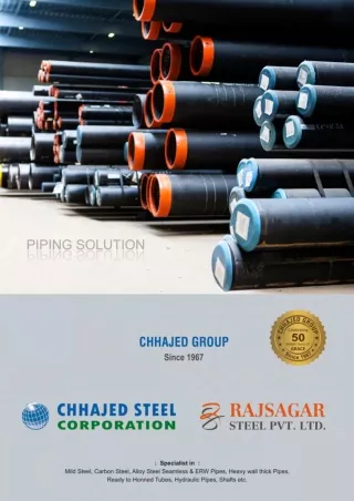
Pipe Manufacturing It consists all about material details, dimension details, type of ends, schedules/thicknesses, branch offs, NDT requirements, various codes/standards being followed for all Piping items. Main Piping items are listed below: • Pipes • Fitting • Flanges • Misc items (Steam traps/Strainers) etc • Bolts • Gaskets • Valves Various codes, symbols in piping design and manufacturing are: • ASME - American society of mechanical engg. • API - American petroleum institute. • ANSI - American National Standards institute.
Pipe fittings
We have just brought the pipes, now we need to solve some more problems. To solve these problems we need the pipe components, which are called Pipes are all straight pieces. PIPE FITTINGS We need some branch connections We need some bend connections
There are various types of fittings for various purposes, some common types are - Elbows/Bends, Tees/Branches, Reducers/Expanders, Couplings, Olets, etc. Anyway, the pipes and fittings are in place, but the ends are yet to be joined with the Tank nozzles. We now have to complete the end connections. These, in piping term, we call TERMINAL CONNECTIONS.
But if we want to control the flow from Tank-1 to other tanks. We need some arrangement to stop the flow if needed These are flanged joints This is a welded joint
Flanges • Flanges provide a bolted, separable joint in piping. The most of valves have flanged ends and must have a companion or matching flange attached. A gasket is then inserted between them, and the bolts are tightened to form a flanged joint. When to use Flanges? • Where there is a clear need for removal of valves or equipment, for access of maintenance, or for blinding. • As all flanged connections are potential leak source, their use should be kept to the minimum needed for safe and reasonably convenient operation and maintenance.
Types of Flanges • Neck Weld (NW):The welding neck flanges are attached by butt-welding to the pipes. • Socket Weld (SW):The socket weld flanges are welded only on one side and are not recommended for severe services. These are used for small-bore lines only. • Slip-on (SO):The slips on flanges are attached by welding inside as well as outside. • Lap-Joint (LJ):The lap joint flanges are used with the stub ends when piping is of a costly material.
Neck weld Flange Socket weld Flange Slip-on Flange
Slip-on Flange Lap Joint Flange
Flange Material: Flanges are made of carbon steel forging having a highly refined grain structure and generally excellent physical properties well in excess of recognized minimum requirements. In addition, flanges in 300 psi and higher pressure classes can be made of Chrome- Molybdenum Forged steel (ASTM A182 GRADE F5A). • • Bolts & Gaskets Choice of bolting material is governed by service fluid and its temperature. The most commonly used bolts for flanges in piping are the ASTM A193 Gr.B7 Stud bolts which fall into the high strength group. The temperature range is from –29°C to 454°C. A gasket is a thin circular disc, made up of soft compressive material. The most of valves have flanged ends and must have a companion or matching flange attached. A gasket is then inserted between them, and the bolts are tightened to form a flanged joint. • • •
But if we want to control the flow from Tank-1 to other tanks. We need some arrangement to stop the flow if needed These are flanged joints This is a welded joint To control the flow in a pipe line we need to fit a special component. That is called - VALVE
VALVES • Valves stop or open and regulate flow. Some of the basic valve types are gate, globe, check, Ball, Plug, etc. • GATE VALVE: It is usually manually operated and is designed for open or shut operation. Flow can enter either end of the gate body. • GLOBE VALVE: is for throttling. Good examples of globe valves are the faucets on washbasin which throttle or adjust the flow to suit a person’s needs. Flow must enter the valve and flow up, against the seat, and change the direction again to the outlet. • CHECK VALVE: “checks” flow. It lets flow go one way and will not let it reverse. When you have a check valve in a line, you have made a one-way street. The flow can go one way.
VALVES In piping systems, valves are used to stop or open and regulate the flow. Some of the basic valve types are gate, globe, check, Ball, Plug, etc. Type of vales:
Type of valves Isolation Valves: • Gate Valve • Ball Valve • Plug Valve • Piston Valve • Diaphragm Valve • Butterfly Valve • Pinch Valve Regulation Valves: •Globe Valve •Needle Valve •Butterfly Valve •Diaphragm Valve •Piston Valve •Pinch Valve
Type of valves Non return Valve: • Check Valve Special Purpose Valves: • Multi-port Valve • Flush Bottom Valve • Float Valve • Foot Valve • Line Blind Valve • Pressure / Vacuum Relief Valve
Type of valves globe valve
Type of valves Butterfly valve
Type of valves Check valve
Type of valves Screw down valve
Type of valves Fire hydrant valve Throttle valve
There are many types of valves, categorized based on their construction and functionality, Those are - Gate, Globe, Check, etc. Other than valves another important line component of pipe line is a filter, which cleans out derbies from the flowing fluid. This is called a STRAINER
When some fluid is flowing in a pipe we may also like know the parameters like, pressure, temperature, flow rate etc. of the fluid.
Here are some of the pipe supporting arrangements. There can be numerous variants. All depend on piping designer’s preference and judgement.
Piping Flexibility All piping must be designed for thermal expansion under start up, operating and shut down conditions without over stressing the piping, valves or equipments. Adequate flexibility for the steam out conditions at temp of 120 deg c provisions for expansion or contraction shall normally be made with bends, off-sets etc. DESIGN CONDITIONS: • Operating conditions: - normal design conditions of pressure & temperature are expected to co-exist. These usual operations include all manipulations & control functions such as throttling, blowing, and bypassing. • Transient conditions: - such as those incidentals to start up, steam out, abnormal load, etc .
Piping Layout • Detailed equipment layout including key plan. • Preparation of piping studies. • Fixing the orientation. • Piping supports. • Line isometric & vessel trims. • Model preparations & field engineering. • BASIS OF EQUIPMENT LAYOUT: • Equipment layout shall be developed based on the following data: • P&IDs ( Piping & instrumentation diagram ) • Overall plot plan • Equipment data sheets • Indicative equipment layout
Piping Layout Pipe sizes are selected. Then pipe material and pipe wall thickness are selected. Types of Valves are planned Also the types of instruments required are planned We represent the whole thing in a drawing which is called Piping and Instrumentation Drawing, in short P&ID. For P&ID generation we may use suitable software such as AutoCAD, Edraw, Smartplant etc. All the pipe lines system information in the drawing has to enter for P&ID . The P&ID drawing is an Intelligent drawing which carries all the information about Pipe size, Pipe Material, Fittings, Valves, Strainer, Flowing Fluid, etc.
This is screen picture of P&ID made by SPP&ID If we click on any line it will show the Data embedded.
Pipe Coating and Colour No internal coating is done for pipes to carry air, fuel and lubricants. MS pipes are galvanized for water. But SS or copper -nickel pipes do not require galvanization. External coatings are required to identify each system. Sometimes, bands are used for identification instead of coatings. • • • Yellow Maroon Deep Brown Silver White Green Blue Red Signal
Pipe Stress Analysis To check and confirm the pipe is not going to fail due to various loading. In the process of Analysis we apply various postulated loading on the pipe and find out the stress resulted from these loading. Then we check with governing codes if those stresses generated are acceptable or not. We check support load & movement for various loading condition. We also check out the terminal point loading generated from pipe to the equipment connected to the pipe. This loading are to be within acceptable limits of the equipment suggested by the vendors. We also find out the pipe growth due to change in temperature and need to keep the movement of pipe within acceptable limits. Pipe Stress Analysis is an Interactive and Iterative process. Each step is checked If a check fails we have to go back, modify the layout and restart the analysis.
PIPE STRESS ANALYSIS Inputs Tools we can use Geometric layout of Pipe PIPSYS - is an integrated pipe stress analysis module of PLADES 2000 Pipe supporting configuration CEASER - Commercial Piping analysis software Pipe Diameter and Thickness Pressure inside Pipe Outputs Cold and Hot temperatures of Pipe Weight of Pipe and insulation Stress of the pipe at various loading conditions Weight of carrying Fluid Load at various supports and restrains. Pipe material Property (Young’s Modulus, Thermal Expansion Coefficient) Movement of pipe at support locations Pipe terminal point loading.