Download
1 / 12
120 likes | 122 Views
Learn how to draw accurate auxiliary views for surfaces with curved edges. Follow step-by-step instructions and examples.

E N D
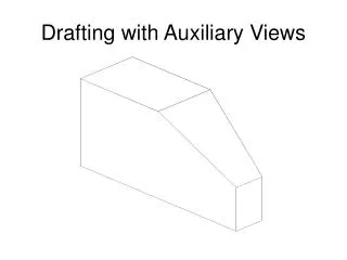
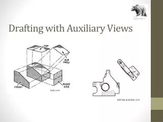
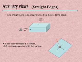
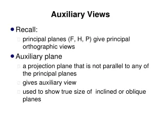
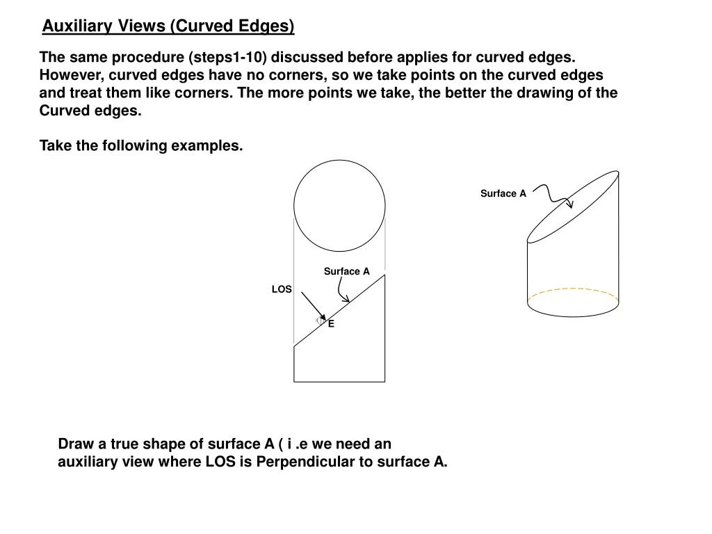
Surface A LOS E Auxiliary Views (Curved Edges) The same procedure (steps1-10) discussed before applies for curved edges. However, curved edges have no corners, so we take points on the curved edges and treat them like corners. The more points we take, the better the drawing of the Curved edges. Take the following examples. Surface A Draw a true shape of surface A ( i .e we need an auxiliary view where LOS is Perpendicular to surface A.
6' 5' 7' 8' 4' 9' 3' 10' 2' 11 + 1 2 10 3 9 4 8 5 7 6 1 2 3 4 5 6 7 8 9 10 11 1 - choose points on curved edges - connect projection lines between views
7' 6' 8' 5' 4' 9' 3' 10' 2' 11 + 1 2 10 3 9 4 8 5 7 6 1 2 3 4 5 6 7 8 9 10 11 2 • Choose LOS ( in this case LOS is • perpendicular to surface A to get true shape) • Draw projection lines from chosen points • on curved edges parallel to LOS.
7' 6' 5' 8' 4' 9' 3' 10' 2' 11 + 1 2 10 3 9 4 8 5 7 6 RL2 1 2 3 4 5 6 7 8 RL1 9 10 11 3 - Draw RL1 perpendicular to projection lines // LOS • Draw RL1 perpendicular to projection lines • between the two views.
7' 6' 5' 8' 4' 9' 3' 10' 2' 11 + 1 2’ 1 3’ 4’ 5’ 2 10 6’ 3 9 4 2 8 7’ 5 7 6 RL2 8’ 3 9’ 4 5 10’ 6 7 8 11 1 9 2 10 3 4 5 6 7 8 RL1 9 10 11 4 - Measure distance from RL2 - Transfer distance to RL1
7' 6' 5' 8' 4' 9' 3' 10' 2' 11 + 1 2’ 1 3’ 4’ 5’ 2 6’ 10 3 9 4 7’ 8 5 2 7 6 RL2 8’ 3 9’ 4 10’ 5 6 7 8 11 1 9 10 2 3 4 5 6 7 8 RL1 9 10 11 5 - Connect points
6' 7' 8' 5' 4' 9' 3' 10' 2' 1 + 11 RL2 2 10 3 9 4 8 5 7 6 1 2 3 RL1 4 5 6 7 8 9 10 11 OR 3' - Draw RL1 • Draw RL1
6' 7' 5' 8' 4' 9' 3' 10' 2' 1 + 11 RL2 2’ 3’ 1 4’ 2 10 5’ 3 9 4 6’ 8 5 7 6 2 7’ 8’ 3 9’ 4 5 10’ 6 7 1 2 11 8 9 3 RL1 10 4 5 6 7 8 9 10 11 OR 4' - Measure distance from RL1 • Transfer distance to RL1
6' 7' 5' 8' 4' 9' 3' 10' 2' + 1 11 RL2 2’ 3’ 1 4’ 2 10 5’ 3 9 4 6’ 8 5 7 6 7’ 2 8’ 3 9’ 4 10’ 5 6 7 1 2 11 8 9 3 RL1 10 4 5 6 7 8 9 10 11 OR 5' • Connect Point
Run //CE-WSINST Auxiliary View - http://faculty.kfupm.edu.sa/CE/almanasa/ - Run //CE-WSINST - Complete - Partial (1) Identify line of sight (2) Draw reference line (3) Project lines from each view (1) Create layers (1) Choose color for projection. (2) Create layers (2) Choose another color for point numbers. - Draw offset Through (any distance) and choose point for RL 2 & RL 1 -
- Choose layer for text Give the Same Number on all layer - Go to Tool pull down drafting setting object snap perpendicular - OR ONSAP setting perpendicular (SELECT) - Go to Construction layer (1) - Type DI (distance) or from the Tool bar add Inquiry bar & choose DI
- Go perpendicular Go offset same dist. up and draw - Extent line to new point Give a point number as text. - For curved line choose PL commands to draw lines - Type PEDIT Choose line (to show it smooth curve) F - To change some lines to hidden . Modify properties Line type hidden - Mirror Choose line shift choose ….. specify 1st point 2nd point around the x-x line Enter