Download
1 / 39
400 likes | 581 Views
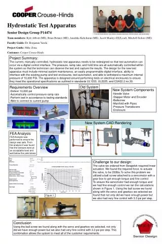
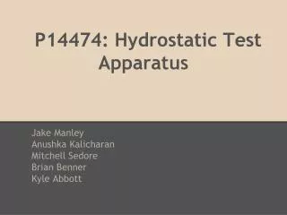
Design Review UL Vibration Test Apparatus. May 13, 2013 1:30PM Est. Project & Team Information. Project: UL Vibration Test Apparatus Project Number: 13471 Customer: Eaton Corporation (previously Cooper Crouse-Hinds Industries) Customer Contacts: Joe Manahan Ed Leubner

E N D
Design ReviewUL Vibration Test Apparatus May 13, 2013 1:30PM Est.
Project & Team Information Project: UL Vibration Test Apparatus Project Number: 13471 Customer: Eaton Corporation (previously Cooper Crouse-Hinds Industries) Customer Contacts: Joe Manahan Ed Leubner RIT Faculty Guide: Dr. Benjamin Varela Project Team: Walter Bergstrom Sean Coots Spencer Crandell Mark Ellison UL Vibration Test Apparatus
Presentation Overview • Detailed Design Overview • Final Design • Testing • Improvements & Future Work • Budget Appendix: UL Test Stand and Project Background UL Vibration Test Apparatus
Design Review Discussion • Discussed Design: • Adjustment Mechanism • Crank Arm • Key Action Items: • Adjustment Mechanism Strength • Crank Arm • Actions Taken: • Crank Arm to be a single piece UL Vibration Test Apparatus
Final Design UL Vibration Test Apparatus
Final Design (video) UL Vibration Test Apparatus
Adjustment Mechanism • Allows for adjustment in eccentricity in order to • account for tolerance stack-ups and wear • Set screw used for fine adjustment • Two socket head cap screws for locking the system in place • Nord Lock washers to prevent loosening of adjustment mechanism UL Vibration Test Apparatus
5/8-11 Nord Lock Washers • Rated for maximum locking at 197 ft-lbs with 20900lb clamping force • Allows for reusable hardware pelicanparts.com UL Vibration Test Apparatus
Pushrod Connection • Extension rod is threaded into both the pushrod and pipe collar to allow for adjustment • Pushrod position can vary in shaft supports to allow for additional adjustment • Pushrod is robust and will not deflect during operation • Nuts used to lock threaded portion at the end of the pushrod in place UL Vibration Test Apparatus
Testing • Displacement testing completed on the system • As motor implementation is not within the scope of this project, frequency was not validated • Test frame rigidly fastened to testing table • Angle steel welded into frame shape • Aluminum cantilever with flange connection • Dial indicators used in two locations to verify the displacement across the system • Contacting linear slider box • Contacting collar at connection to vertical conduit UL Vibration Test Apparatus
Testing Dial Indicator Contacting Conduit Collar Dial Indicator Contacting Slider Box UL Vibration Test Apparatus
Flange Connection Test Frame Cantilever • Test 1: Verify zero-displacement • Centering dowels mated between adjustment mechanism and rotating disk to signify zero-displacement • Dial indicators showed zero displacement for the system • Test 2: Verify 3 displacement values • 0.016”: found that dial indicators give very low value for displacement (.004-0.008”) • 0.100”: again found that measured values were lower than expected (0.045-0.055”) • 0.250”: met expected displacement value within ± 0.010” • Test 3: Verify torque • Torque wrench used not ideal; not precise enough to measure low torque range • Did verify that the required torque to drive the steady-state system is below ~2 lbf-ft Testing Table Vertical Conduit Conduit Collar UL Vibration Test Apparatus
Testing Conclusions • Zero-displacement point is validated • Displacement measurements do not agree at low eccentric values, but they do at higher distances • Postulated that the dial indicators are not precise enough to accurately measure low eccentric distances • Torque measurement has a high degree of uncertainty due to the low level of precision associated with the torque wrench used during testing • Recommended: • Purchase more precise dial indicator (re-test) • Purchase more precise torque wrench (re-test) UL Vibration Test Apparatus
Frame Design 34” 44” UL Vibration Test Apparatus
Frame Design Advantages: • Allows for a single technician to mount the luminaire • Extra support of U-channel decrease vibration of system • Rubber pads in-between supporting beams help in dampening the system • More space efficient than current design • *Approximately 44” X 34” footprint • Footprint may become larger due to resonate frequency of design (to be tackled by next senior design group) UL Vibration Test Apparatus
Motor Selection • 3-Phase, 240V AC Motor • Steady-state period • No acceleration of system • lbfft • This corresponds to a motor horsepower of 0.41,therefore a 1hp motor is desired • Where r= in (stroke of crank), θis angle of rotation of the motor ( • Start-up period • Where: • Assuming 50-60 seconds to reach 2000RPM, Treq3 lbfft UL Vibration Test Apparatus
At 2000RPM, a general purpose 1HP AC Baldor motor will produce 90ozft 5.7lbft torque • Our estimated range for required start-up torque is highlighted in yellow • At ~5.7lbfttorque, it is estimated that 2000RPM will be reached in approximately 30 seconds • A variable-frequency drive will be used to obtain the required 2000RPM speed UL Vibration Test Apparatus
Recommended Motor UL Vibration Test Apparatus
Where ka, kb and kc are Marin factors for surface condition, size, and loading conditions, respectively. • l1=2 , l2=4 , σmin, σmax, Sy, Sut can be found in Appendix UL Vibration Test Apparatus
Identified Improvements • Install a brake • Plate or coat steel parts (zinc plating) • Development of 2 section maintenance compartment • Removable tapered dowels for gauging • Possible addition of counter weight • Fixed dial gauge for reading smaller deflections • Isolate motor from drive shaft
Needed Before Running Final Testing • Reassemble using Loctite • Use lock nuts or lock washers with hardware holding linear bearings in place • Ensure all bearings are properly lubricated • Bolt system to floor
Next Steps of Project • Manufacture frame • Install motor with motor base • Choose shaft coupling and install • Choose and install brake • Choose motor control and install • Develop other features designated by customer input (LabView integration)
Things We Learned • Consult machinist before diving into manufacturing part/system • Many parts may need to be machined as an assembly • Dowels are useful for location and assembly but have limitations in their use • Check hardness of steel from scrap bin before machining them!!!
Project Cost Cooper has paid as of now: $3,000.00 Cost of project to date: $3,076.26 Estimated total cost: ~$8,000.00
Open Discussion • Any questions? • Design concerns not discussed? • Implementation of LabView? UL Vibration Test Apparatus
Appendix UL Test Standard and Project Background
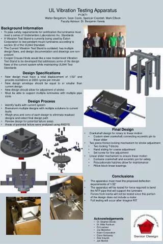
Project Background • To pass safety requirements for certification the luminaires must meet a series of Underwriters Laboratories Inc. Standards. • A Vibration Test Stand is currently being used by Cooper Crouse-Hinds to test pendant mount luminaires according to section 33 of the UL844 Standard. • The Current Vibration Test Stand is outdated, has multiple design flaws, and design documentation and drawings are non-existent. • Cooper Crouse-Hinds would like a new modernized Vibration Test Stand to be developed that addresses some of the design flaws of the current system while maintaining UL844 Test Standards. This new Design must also have a LabView interface and control capability integrated into the system. UL Vibration Test Apparatus
Design Goals over Winter/Spring MSD Note: It has been decided that this apparatus will be developed in multiple Senior Design Sequences. • Provide customer with two design concepts for vibration mechanism • Develop a final design of the vibration mechanism. • Design a steel test frame that will support the vibration mechanism and the vertical conduit. • Design but do not develop steel frame for entire vibration test machine. • Develop a full set of engineering drawings. • Calculate and select the required drive train system components. • Purchase materials, machine components, and assemble the vibration mechanism and test frame. • Test the mechanism to ensure that it meets 1/32” deflection requirement UL Vibration Test Apparatus
Summary of UL844 Vibration Test Standard LUMINAIRES FOR USE IN HAZARDOUS (CLASSIFIED) LOCATIONS – UL 844 Section 33 – Vibration Test Standards • Luminaire is to be subjected to 35 hours of vibration testing. • Luminaire assembly is to be attached to a 26-1/2” long conduit via NPT threading. The other end of the NPT threaded pipe is to be secured to the hub of a rigid mounting frame so that the conduit hangs vertically. The conduit should correspond to the smallest size of threaded conduit hub that is designed to attach to the Luminaire being tested. • The horizontal force to be applied to the system in order to obtain the deflection must me located 4” above the location of the conduit where the Luminaire attaches. • The deflection must be 1/32” with 1/16” total deflection per cycle. • The system must run at 2000 cycles/min. UL Vibration Test Apparatus
UL844 Vibration Test Standard UL Vibration Test Apparatus
Design Flaws Associated with Original Design • Difficult for one technician to set up test • Lubricant not contained • Machine components exposed to contaminants • Belts used (slipping) • Uses single speed motor with a speed reducer • Frequency adjustment dial held in place with rope • No displacement adjustment • Attachment collar may experience minor buckling • Does not accounted for part wear and tolerance stack up UL Vibration Test Apparatus
PUGH Matrix: Rotational to Linear Motion Mechanism UL Vibration Test Apparatus
PUGH Matrix: Slider Mechanism UL Vibration Test Apparatus
PUGH Matrix: Displacement Adjustment Mechanism UL Vibration Test Apparatus
Risk Assessment UL Vibration Test Apparatus
Lubrication • Drive Shaft Bearings: Double sealed flange mount bearings with easy access grease zerk fittings. • Linear Bearings: Double sealed closed bearings with easy access grease zerk fittings. • Crank Arm Bearings: Double Sealed roller bearings pre-packed with grease . Easy access for lubrication by taking off Polycarbonate cover. UL Vibration Test Apparatus