Download
1 / 25
1.81k likes | 3.57k Views
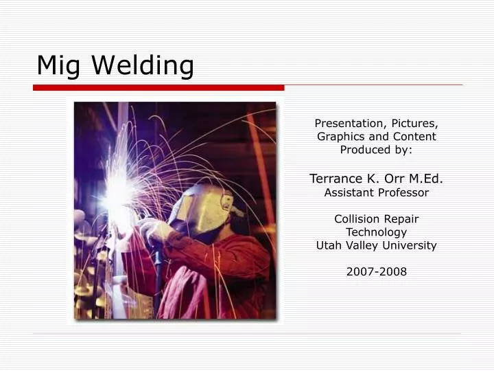
Mig Welding. Presentation, Pictures, Graphics and Content Produced by: Terrance K. Orr M.Ed. Assistant Professor Collision Repair Technology Utah Valley University 2007-2008. Why Mig Weld?. Wire-feed Fusion Welding Process. Minimizes the loss of strength in High Strength Steel.

E N D
Mig Welding Presentation, Pictures, Graphics and Content Produced by: Terrance K. Orr M.Ed. Assistant Professor Collision Repair Technology Utah Valley University 2007-2008
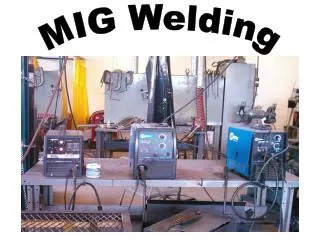
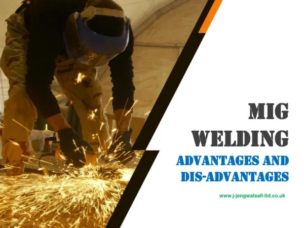
Why Mig Weld? • Wire-feed Fusion Welding Process. • Minimizes the loss of strength in High Strength Steel. • Minimized Metal Distortion. • Vehicle Manufacturers demand its use. • Faster Procedure. UVU CRT 2009
Mig Welding • Uses a constant voltage source. • Wire feed rate sets the current. • Continuous flow of shielding gas. • Continuous supply of wire. UVU CRT 2009
Mig Internals • Straight or Reverse Polarity. • Wire Tension Adjustment. • Continuous Wire. UVU CRT 2009
Electrode Wire Sizes • There are three common sizes of MIG wire. • .035 • .030 • .023 .023 is recommended for collision repair work. UVU CRT 2009
Mig Welding Adjustments • Wire Feed Speed • Voltage • Continuous/Spot • Distance from coupon • Push/Pull UVU CRT 2009
Mig Welder Settings • Voltage Adjustment • Wire Feed Adjustment UVU CRT 2009
Welder Suggested Settings • Each welder has suggested wire feed and voltage settings dependant on the thickness of the material, the shielding gas, and type of wire used. • This is found on the lid of the welder. UVU CRT 2009
Tuning the Welder • Tune For Specific Metal To Be Joined • Set Voltage and Wire Speed • Make Sample Weld • Readjust Settings as Necessary • Practice the Push and Pull Technique UVU CRT 2009
Gun Technique Pushing the Weld Pulling the Weld • Heat into Work • Easier Burn Through • Faster Rate of Travel • Heat into Puddle • Slower Rate of Travel UVU CRT 2009
Weld Positions • Standard Flat Position. • Vertical – Start at the top and move down. UVU CRT 2009
Weld Positions • Horizontal – Used on vertical panels. • Overhead – Can be a difficult weld to master. UVU CRT 2009
Defects – High Heat • A voltage setting that is too high will result in holes melted through the panel. UVU CRT 2009
Defects – Good Weld • This is an example of a good weld. Look for an even bead without spatter, and an even heat affect zone. Heat Effect Zone UVU CRT 2009
Defects – High Wire Speed • High wire speed will create a cooler weld with very little penetration and excessive surface bead buildup. UVU CRT 2009
Defects – No Gas • A weld without shielding gas will be porous and very uneven. UVU CRT 2009
Travel Speed • Travel Speed is another variable that can affect your weld quality. • Too slow can cause excessive penetration and burn-through. • Too fast can cause excessive bead buildup without adequate penetration. • It is a combination of Travel Speed, Voltage, and Wire Speed that creates a good weld. UVU CRT 2009
Defects – Speed too Fast • If the travel speed is too fast inadequate heat will create a tall bead with no penetration. UVU CRT 2009
Defects – Speed too Slow • Travel speed that is too slow will result in a wide bead with a large heat affect zone. UVU CRT 2009
Weld Penetration • Weld penetration should also be checked to ensure complete metal fusion without excessive heat. • This picture shows a good even ribbon of penetration. UVU CRT 2009
Weld Penetration • This picture is showing excessive penetration. • The weld puddle is literally falling through the metal and if left unchecked will result in a hole. UVU CRT 2009
Problem Solving • Clean The Metal • Coatings • Rust-proofing • Grime • Rust • Don’t Grind off Galvanizing UVU CRT 2009
Problem Solving - Weld Fit Up • The term Fit Up refers to the preliminary alignment and securing of the panels to be welded. • Proper fit up can greatly enhance the weld quality. UVU CRT 2009
Weld Fit Up • Assure Good Fit Up • Tightly Clamp the Metal Using Locking Pliers • Grind Off Burrs • Use Metal Screws • Use Clecos UVU CRT 2009
References • Miller Electric Mfg. Co. Education. http://www.millerwelds.com/education/library.html, 2006. • Lincoln Electric Co. Lincoln Welders. http://www.lincolnelectric.com/, 2006. • Inter Industry Conference on Automotive Collision Repair. I-CAR Online Training. http://www.i-car.com/, 2006. UVU CRT 2009