Download

1 / 14

E N D
74 MAP/BARO SENSORS
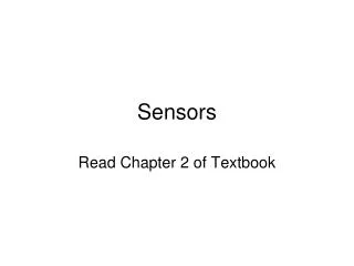
Figure 74-1 (a) As an engine is accelerated under a load, the engine vacuum drops. This drop in vacuum is actually an increase in absolute pressure in the intake manifold. A MAP sensor senses all pressures greater than that of a perfect vacuum. (b) The relationship between absolute pressure, vacuum, and gauge pressure.
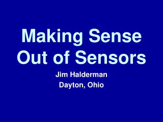
Figure 74-2 A clear plastic MAP sensor used for training purposes showing the electronic circuit board and electrical connections.
TECH TIP: If It’s Green, It’s a Signal Wire Ford-built vehicles usually use a green wire as the signal wire back to the computer from the sensors. It may not be a solid green, but if there is green somewhere on the wire, then it is the signal wire. The other wires are the power and ground wires to the sensor.
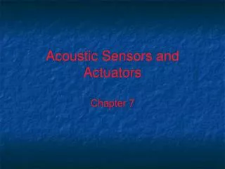
Figure 74-3 MAP sensors use three wires: 1. 5-volt reference from the PCM 2. Sensor signal (output signal) 3. Ground. A DMM set to test a MAP sensor. (1) Connect the red meter lead to the V meter terminal and the black meter lead to the COM meter terminal. (2) Select DC volts. (3) Connect the test leads to the sensor signal wire and the ground wire. (4) Select hertz (Hz) if testing a MAP sensor whose output is a varying frequency; otherwise keep it on DC volts. (5) Read the change of voltage (frequency) as the vacuum is applied to the sensor. Compare the vacuum reading and the frequency (or voltage) reading to the specifications.
Figure 74-5 Shown is the electronic circuit inside a ceramic disc MAP sensor used on many Chrysler engines. The black areas are carbon resistors that are applied to the ceramic, and lasers are used to cut lines into these resistors during testing to achieve the proper operating calibration.
TECH TIP: Use the MAP Sensor as a Vacuum Gauge A MAP sensor measures the pressure inside the intake manifold compared with absolute zero (perfect vacuum). For example, an idling engine that has 20 inches of mercury (in. Hg) of vacuum has a lower pressure inside the intake manifold than when the engine is under a load and the vacuum is at 10 in. Hg. A decrease in engine vacuum results in an increase in manifold pressure. A normal engine should produce between 17 and 21 in. Hg at idle. Comparing the vacuum reading with the voltage reading output of the MAP sensor indicates that the reading should be between 1.62 and 0.88 volt or 109 to 102 Hz or lower on Ford MAP sensors. Therefore, a digital multimeter (DMM), scan tool, or scope can be used to measure the MAP sensor voltage and be used instead of a vacuum gauge.NOTE: This chart was developed by testing a MAP sensor at a location about 600 feet above sea level. For best results, a chart based on your altitude should be made by applying a known vacuum, and reading the voltage of a known-good MAP sensor. Vacuum usually drops about 1 inch per 1,000 feet of altitude.Vacuum (in. Hg) GM (DC volts) Ford (Hz)0 4.80 156–1591 4.522 4.463 4.264 4.065 3.88 141–1436 3.667 3.508 3.309 3.1010 2.94 127–13011 2.7612 2.5413 2.3614 2.2015 2.00 114–11716 1.8017 1.6218 1.42 108–10919 1.2020 1.10 102–10421 0.8822 0.66
TECH TIP: Use the MAP Sensor as a Vacuum Gauge A MAP sensor measures the pressure inside the intake manifold compared with absolute zero (perfect vacuum). For example, an idling engine that has 20 inches of mercury (in. Hg) of vacuum has a lower pressure inside the intake manifold than when the engine is under a load and the vacuum is at 10 in. Hg. A decrease in engine vacuum results in an increase in manifold pressure. A normal engine should produce between 17 and 21 in. Hg at idle. Comparing the vacuum reading with the voltage reading output of the MAP sensor indicates that the reading should be between 1.62 and 0.88 volt or 109 to 102 Hz or lower on Ford MAP sensors. Therefore, a digital multimeter (DMM), scan tool, or scope can be used to measure the MAP sensor voltage and be used instead of a vacuum gauge.NOTE: This chart was developed by testing a MAP sensor at a location about 600 feet above sea level. For best results, a chart based on your altitude should be made by applying a known vacuum, and reading the voltage of a known-good MAP sensor. Vacuum usually drops about 1 inch per 1,000 feet of altitude.Vacuum (in. Hg) GM (DC volts) Ford (Hz)0 4.80 156–1591 4.522 4.463 4.264 4.065 3.88 141–1436 3.667 3.508 3.309 3.1010 2.94 127–13011 2.7612 2.5413 2.3614 2.2015 2.00 114–11716 1.8017 1.6218 1.42 108–10919 1.2020 1.10 102–10421 0.8822 0.66
TECH TIP: Use the MAP Sensor as a Vacuum Gauge A MAP sensor measures the pressure inside the intake manifold compared with absolute zero (perfect vacuum). For example, an idling engine that has 20 inches of mercury (in. Hg) of vacuum has a lower pressure inside the intake manifold than when the engine is under a load and the vacuum is at 10 in. Hg. A decrease in engine vacuum results in an increase in manifold pressure. A normal engine should produce between 17 and 21 in. Hg at idle. Comparing the vacuum reading with the voltage reading output of the MAP sensor indicates that the reading should be between 1.62 and 0.88 volt or 109 to 102 Hz or lower on Ford MAP sensors. Therefore, a digital multimeter (DMM), scan tool, or scope can be used to measure the MAP sensor voltage and be used instead of a vacuum gauge.NOTE: This chart was developed by testing a MAP sensor at a location about 600 feet above sea level. For best results, a chart based on your altitude should be made by applying a known vacuum, and reading the voltage of a known-good MAP sensor. Vacuum usually drops about 1 inch per 1,000 feet of altitude.Vacuum (in. Hg) GM (DC volts) Ford (Hz)0 4.80 156–1591 4.522 4.463 4.264 4.065 3.88 141–1436 3.667 3.508 3.309 3.1010 2.94 127–13011 2.7612 2.5413 2.3614 2.2015 2.00 114–11716 1.8017 1.6218 1.42 108–10919 1.2020 1.10 102–10421 0.8822 0.66
REAL WORLD FIX: The Cavalier Convertible Story The owner of a Cavalier convertible stated to a service technician that the “check engine” (MIL) was on. The technician found a diagnostic trouble code (DTC) for a MAP sensor. The technician removed the hose at the MAP sensor and discovered that gasoline had accumulated in the sensor and dripped out of the hose as it was being removed. The technician replaced the MAP sensor and test drove the vehicle to confirm the ) repair. Almost at once the check engine light came on with the same MAP sensor code. After several hours of troubleshooting without success in determining the cause, the technician decided to start over again. Almost at once, the technician discovered that no vacuum was getting to the MAP sensor where a vacuum gauge was connected with a T-fitting in the vacuum line to the MAP sensor. The vacuum port in the base of the throttle body was clogged with carbon. After a thorough cleaning, and clearing the DTC, the Cavalier again performed properly and the check engine light did not come on again. The technician had assumed that if gasoline was able to reach the sensor through the vacuum hose, surely vacuum could reach the sensor. The technician learned to stop assuming when diagnosing a vehicle and concentrate more on testing the simple things first.
TECH TIP: Visual Check of the MAP Sensor A defective vacuum hose to a MAP sensor can cause a variety of driveability problems including poor fuel economy, hesitation, stalling, and rough idle. A small air leak (vacuum leak) around the hose can cause these symptoms and often set a trouble code in the vehicle computer. When working on a vehicle that uses a MAP sensor, make certain that the vacuum hose travels consistently downward on its route from the sensor to the source of manifold vacuum. Inspect the hose, especially if another technician has previously replaced the factoryoriginal hose. It should not be so long that it sags down at any point. Condensed fuel and/or moisture can become trapped in this low spot in the hose and cause all types of driveability problems and MAP sensor codes. When checking the MAP sensor, if anything comes out of the sensor itself, it should be replaced. This includes water, gasoline, or any other substance.