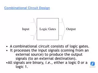
Download
1 / 11
160 likes | 488 Views
X+Y’. 00001111. 00001111. X. 11001111. 11001100. 00110011. Y. (X+Y’) . Z. Y’. 01000101. Z. 01010101. 01010101. Z. 01100101. X’. 11110000. F. Y. 00110011. 00100000. X’. Y. Z’. Z’. 10101010. Combinational Circuit Analysis Example. Given this logic circuit we can :

E N D
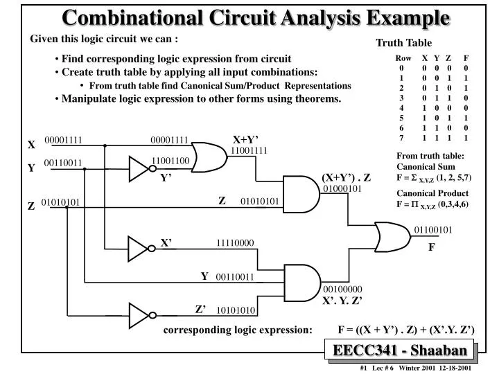
X+Y’ 00001111 00001111 X 11001111 11001100 00110011 Y (X+Y’) . Z Y’ 01000101 Z 01010101 01010101 Z 01100101 X’ 11110000 F Y 00110011 00100000 X’. Y. Z’ Z’ 10101010 Combinational Circuit Analysis Example • Given this logic circuit we can : • Find corresponding logic expression from circuit • Create truth table by applying all input combinations: • From truth table find Canonical Sum/Product Representations • Manipulate logic expression to other forms using theorems. Truth Table Row X Y Z F 0 0 0 0 0 1 0 0 1 1 2 0 1 0 1 3 0 1 1 0 4 1 0 0 0 5 1 0 1 1 6 1 1 0 0 7 1 1 1 1 From truth table: Canonical Sum F = SX,Y,Z (1, 2, 5,7) Canonical Product F = PX,Y,Z (0,3,4,6) corresponding logic expression: F = ((X + Y’) . Z) + (X’.Y. Z’)
X X . Z Y’ Y Y’ . Z X’ X’ . Y . Z’ Z’ Z Combinational Circuit Analysis Example (continued) • The previous circuit logic expression F can be transformed into sum of products by multiplying out (Using T8’) and written as : F = X . Z + Y’. Z + X’.Y. Z’ Realized using a 2-level AND-OR circuit: F = X . Z + Y’. Z + X’.Y. Z’
Combinational Circuit Analysis Example (continued) • The logic expression F for the previous circuit can added out (using T8) and written as: F = ((X+Y’).Z) + (X’.Y.Z’) = (X+Y’+X’).(X+Y’+Y).(X+Y’+Z’).(Z+X’).(Z+Y).(Z+Z’) = 1.1.(X+Y’+Z’).(X’+Z).(Y+Z).1 F = (X+Y’+Z’).(X’+Z).(Y+Z) Realized using 2-level OR-AND circuit.
X (X . Y)’ X Y X’ + Y’ Y X (X + Y)’ Y X X’ . Y’ Y Equivalent Symbols of NAND, NOR Gates NAND Symbols Normal Symbol Alternate NAND Symbol According to DeMorgan’s theorem T13: (X . Y)’ = X’ + Y’ NOR Symbols Normal NOR Symbol Alternate NOR Symbol According to DeMorgan’s theorem T13’: (X + Y)’ = X’ . Y’
NAND-NAND Logic Circuits for Sum of Products • A sum of products logic expression can be realized by NAND gates by replacing all AND gates and the OR GATE in the usual realization with NAND gates as follows: F = A + B + C + D ... where A, B, C, …. are product terms of the input variables e.g. A= x.y.z F = (A’)’+(B’)’+(C’)’+(D’ )’ + …. from T4 = (A’.B’.C’.D’… )’ (from DeMorgan’s theorem T13) This is a 2-level NAND representation.
Alternate Sum of Products Realizations(Applying DeMorgan’s theorem T13 Graphically) AND-OR NAND-NAND
X (X . Z)’ Y’ Y (Y’ . Z)’ X’ (X’ . Y . Z’)’ Z’ Z NAND-NAND Sum of Products Example • The sum of products expression F = X . Z + Y’. Z + X’.Y. Z’ F = ((X . Z)’)’ + ((Y’. Z)’)’ + ((X’.Y. Z’)’)’ double negate T4 F = [(X . Z)’ . (Y’. Z)’ . (X’.Y. Z’)’]’ DeMorgan’s theorem T13 Can be realized using the 2-level NAND-NAND circuit: F = [(X . Z)’ + (Y’. Z)’ + (X’.Y. Z’)’]’
NOR-NOR Circuits for Product of Sums • A product of sums expression can be realized by NOR gates by replacing all the OR gates and the AND gate with NOR gates as follows: F = A.B.C.D. …. Where A, B, C are sum terms of the input variables (e.g. A = x+y+z) F = (A’)’.(B’)’.(C’)’.(D’)’ …. using T4 = (A’ + B’ + C’ + D’ + …)’ (using Demorgan’s theorem T13’) This is a 2-level NOR-NOR representation
Alternate Product of Sums Realizations(Applying DeMorgan’s theorem T13’ Graphically) OR-AND NOR-NOR
Combinational Circuit Synthesis • An example of a combinational circuit description: Create a logic function in 4 input variables N=N3N2N1N0 whose output is 1 only if the input is a prime number. • This function is 1 when the input N =1,2,3,5,7,11 can be written in the canonical sum of products representation as: F = S N3N2N1N0 (1,2,3,5,7,11,13) = N3’N2’N1’N0+ N3’N2’N1N0’+ N3’N2’N1N0 +N3’N2N1’N+N3’N2N1N0+ N3N2’N1N0+ N3N2N1’N0
A Verbal Synthesis Example: An Alarm Circuit • A verbal logic description: • The ALARM output is 1 if the panic input is 1, or if the ENABLE input is 1, the EXISTING input is 0, and the house is not secure. • The house is secure if the WINDOW, DOOR, GARAGE inputs are all 1 • This can be put in logic expressions as follows: ALARM = PANIC + ENABLE . EXISTING’ . SECURE’ SECURE = WINDOW. DOOR. GARAGE ALARM = PANIC + ENABLE . EXISTING’. (WINDOW . DOOR . GARAGE)’ In sum of products form as (by using DeMorgan T13 and multiplying out) : ALARM = PANIC + ENABLE. EXISTING’ . WINDOW’ + ENABLE . EXISTING’. DOOR’+ ENABLE. EXISTING’. GARAGE’