Download
1 / 34
340 likes | 484 Views
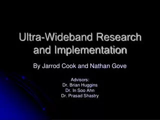
Ultra-Wideband Research and Implementation. By Jarrod Cook and Nathan Gove Advisors: Dr. Brian Huggins Dr. In Soo Ahn Dr. Prasad Shastry. Presentation Outline. Introduction Overview Project Summary Spectrum Overview Modulation Project Issues Time Constraints Sampling Rates

E N D
Ultra-Wideband Research and Implementation By Jarrod Cook and Nathan Gove Advisors: Dr. Brian Huggins Dr. In Soo Ahn Dr. Prasad Shastry
Presentation Outline • Introduction • Overview • Project Summary • Spectrum Overview • Modulation • Project Issues • Time Constraints • Sampling Rates • ADC / DAC issue • Project Schedule • Website Updates • Project Milestones • Model • Block Diagram • Frame Synchronization • Integration with CCS and DSPs • Hardware • 2/3 of Hardware Received • LO Tested • Future Work • Questions?
Introduction to UWB • Ultra-wideband technology is a wireless transmission technique approved for unlicensed use in 2002 under the FCC Part 15 • Ideal for portable multimedia devices because of its inherent low power consumption and high bit rates
Why Research UWB? • UWB is likely to revolutionize the consumer electronic market in the near future. • Wireless USB devices • Wireless communication for High-Definition devices • UWB has the power to eliminate the majority of wires to and from multimedia devices
Overview • Brief History • IEEE 802.15.3a • ECMA 368 and 369 • Consumer Electronics Demand • High data-rate wireless transmissions • Low power consumption for portable devices • UWB allows data rates equivalent to USB 2.0 (480 Mb/s)
Project Summary • The goal of this project is to complete a scaled-down version of a UWB transceiver pair. • Specifically, we are focusing on the following: • Understanding the theory • Simulink modeling • DSP implementation • RF transceiver hardware • Testing
UWB Spectrum Overview • Power spectral density • -41.3 dBm/MHz • FCC part 15 limit • Frequency Range • 3.1 to 10.6 GHz • Sub-bands
Modulation • QPSK or 4-QAM • Gray Coded Mapping • Symbols • Used for data rates from80 to 200 Mb/s • I & Q • 16-QAM or DCM • Used for data rates from320 Mb/s to 480 Mb/s
OFDM • Benefits • Resistance to multi-path fading • Spectrum • Full ECMA standardized UWB spectrum • Scaled-down project spectrum
Project Issues • Due to Time Constraints • Power Limitation • Must be overlooked for this initial project • Output of quadrature modulators exceed limitations • Transmission Bandwidth / Data Rate • ACD and DAC are not sufficient • Audio Development Kit • UWB Coding Specifications 20% Met • Pseudo-random code / spreading / time interleaving • Forward Error Correcting • Data frame will not include full preambles / headers
Project Issues • Sampling Times • Simulink requires information at equal times • Must be very careful when changing sampling rates • ADC / DAC Issues • DAC • Need to Transmit In Phase and Quadrature Phase Components • DACs can only output real numbers • Two DACs are required • Board only has one DAC • Daughter Boards Required • Both • With faster converters, wider bandwidths possible
Simulink Model • Model • Frame Synchronization • Preamble Complete
Updates on Project Website • UWB Website Updates
DSP Platforms received C6416 DSK Progress
Integration of Simulink with CCS • To use the DSP boards, all that has to be added to the model is the “C6416DSK” block. • Simulink has a blockset for this model • Allows use of ADC and DAC • LEDs • DIP Switches • Software Reset • Running the model automatically launches CCS which converts the model to C-code and uploads it.
Simple DSP Test with CCS • DSP Platform Hardware • Tested with Simulink and Code Composer Studio (CCS) • Used a FIR Filter for a quick test
Simple Test Cont. • Once we figured out how to successfully upload models, we did a quick FIR filter model to test the model. • Sampling rate: 32 kHz • Passband: 0 to 5 kHz • Stopband: 6 kHz • Results • Did a quick frequency sweep of the filter through the DSP to visually confirm the DSP was working
RF Hardware • The RF local oscillator and direct quadrature modulator have arrived.
Local Oscillator Test • The oscillator was tested on the spectrum analyzer to verify that it met the specifications stated in the data sheet. • Data sheet specs: • Tunable from 3.35 to 3.55 GHz • Typical power output: 4.7 dBm (1.5 minimum) • Current draw: 41 mA • Harmonic levels: -7 and -16 dBc
Local Oscillator • Tests performed: • Output frequency vs. tuning voltage • Output power vs. tuning voltage • Harmonic power levels • The frequency vs. tuning voltage matched up with the data sheet nicely • The output power was much lower than the specs (on the order of 0.5 to 1.2 dBm) • Determined the loss of the coax, DC block, and connectors to be around 1 dB. Therefore, results are more normal • Harmonic Power levels matched data sheet specs
Future hardware testing • Quadrature Modulator • Quadrature De-Modulator • Interconnecting all the hardware for testing • Transmission lines as channel before wireless • Signal leaves DSP on a 3.5mm audio jack, and must be received by the modulator with an SMA connector. • Impedance mismatches?
Future Work Previous To Do List Current To Do List • Baseband processor • Increase complexity • Research UWB channels (no longer implementing) • Determine maximum feasible sampling rate • Purchase DSP board • Implement synchronous coherent detection for receiver • RF Transmitter • Find a suitable quadrature modulator • Determine and purchase hardware • Model and Design (no longer implementing) • Fabricate hardware (no longer implementing) • Antenna research (no longer implementing) • RF Receiver • LNA Design and modeling (N. L. I.) • Determine and purchase hardware • Fabricate hardware (N. L. I.) • Testing • Transmitter • Implement Daughterboard DACs and ADCs • Receiver • Complete Frame Synchronization • Pulse on Frame Start • Frame Alignment • Implement Carrier Synchronization • Using the Pilot Signals correct for the phase error. • Testing • System Integration • Full system testing • Bandwidth measurements • Bit Error Rates • Other common communication systems measurements.
Questions ? ? U W B Standards