Download
1 / 36
360 likes | 494 Views
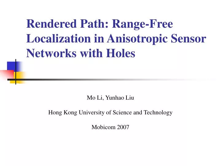
Rendered Path: Range-Free Localization in Anisotropic Sensor Networks with Holes. Mo Li, Yunhao Liu Hong Kong University of Science and Technology Mobicom 2007. Outline. Introduction REP protocol Performance evaluation Conclusions. Introduction.

E N D
Rendered Path: Range-Free Localization in Anisotropic Sensor Networks with Holes Mo Li, Yunhao Liu Hong Kong University of Science and Technology Mobicom 2007
Outline • Introduction • REP protocol • Performance evaluation • Conclusions
Introduction • Sensor positioning is a crucial part of many location-dependent applications that utilize WSNs. • Ex coverage, routing and target tracking • Localization can be divided into • Range-based • Add additional hardware (e.g: GPS) • Range-free • Location information can be obtained • RSSI • Time of arrival or time difference of arrival • Angle of arrival measurements
Introduction- range free • Since there is no way to measure physical distances between nodes. • Existing approaches depend on connectivity based algorithms. • Because the path between a pair of nodes may have to curve around intermediate holes. • Most previous approaches would fail inanisotropic networks. • Ex. DV-Hop
Introduction- DV-Hop • Sensors compute its location by the distance of average hop and triangulation. B X A C
Introduction- DV-Hop • DV-Hop fail in anisotropic networks B B X X A A C C
Introduction • In a isotropic WSNs, • there should have obstacle. • the unbalanced power consumption of sensor would create holes. • there should many external interference cause communication failure. • Authors consider anisotropic network are most likely to exist in practice.
Introduction • In this work, authors propose a distributed range-free scheme for locating sensors in anisotropic WSNs.
REP protocol • Assumption in this paper • The network is anisotropic. • Sensor are deployment with high density. • There are three seed nodes equipped with GPS • Each time sensor estimates one distance to a seed and sensor need to compute three times for triangulation.
REP protocol • REP detects holes and attaches it with an ID All boundary nodes tagged with hole ID and Color Hi Hole 3 t
REP protocol • s broadcasts QUERY message to explore shortest path. s Hole 3 t
REP protocol • All boundary node broadcast V_Hole messages with TTL= k s Hole 3 t
REP protocol • s broadcast QUERY message to explore virtual shortest path. s Hole 3 t
REP protocol • If radii k is too large the virtual shortest path would change to another direction. s s Hole 3 t
REP protocol • Convex Hole • Convex Holes and Concave Holes
REP protocol- single focal point According to the law of cosines O It is short of pointo and an angle sot to adopt the law of cosines.
REP protocol- single focal point • How to find point o? • Author called o as “focal point”. Y. Wang, J. Gao and J. S. B. Mitchell, “Boundary Recognition in Sensor Networks by Topological Methods,” in Proceedings of ACM MobiCom, 2006.
REP protocol- single focal point • Compute angle sot • Firstly, o broadcasts V_Hole message with TTL=k value. O
REP protocol- single focal point • Compute angle sot • Secondly, s broadcastsQUERY message to find a virtual shortest path. O
REP protocol- single focal point • Compute angle sot • Last, we compute angle sot. O
REP protocol- single focal point • Compute angle sot
REP protocol-two focal points We can compute αand β by the previous way.
Performance evaluation Basic setting 5376 nodes (average degree = 12.9) Two holes 4697 nodes (average degree = 12.9) Two holes (one concave) 5142 nodes (average degree = 12.8).
Performance evaluation • A large radius provides a better estimation.
Performance evaluation • Localization performance under REP distance measurement.
Performance evaluation • Related Work DV-Hop • D. Niculescu and B. Nath, “DV Based Positioning in Ad Hoc Networks,” Journal of Telecommunication Systems, 2003. B X A C
Conclusions • In this paper author • propose a range-free localization scheme in anisotropic sensor networks. • The most important contributions • necessity of ranging devices • dependence on large numbers of uniformly deployed seed nodes • assumption of isotropic networks.