Download
1 / 17
930 likes | 2.46k Views
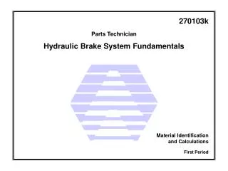
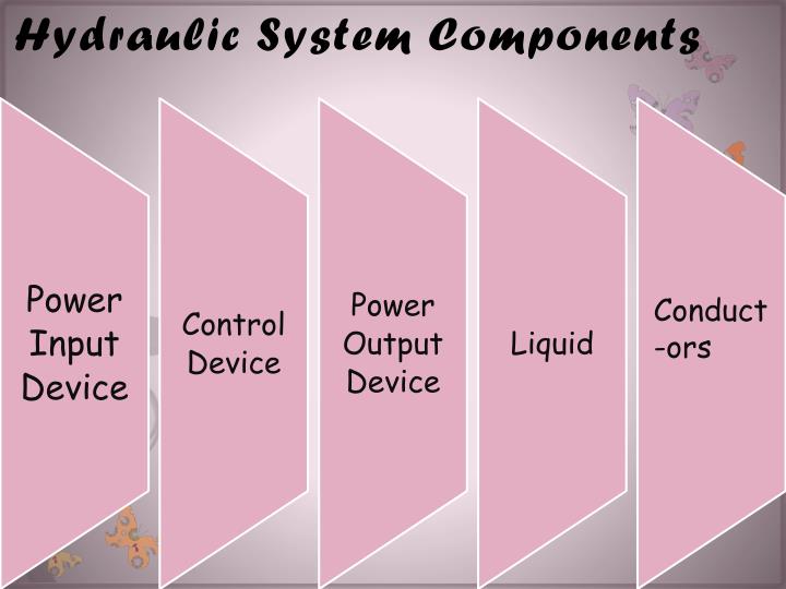
Hydraulic System Components. Conduct-ors. Power Input Device :

E N D
Hydraulic System Components Conduct-ors
Power Input Device: • The pump and motor together are called the power input device; the pump provides power to the hydraulic system by pumping oil from the reservoir/tank. The pump’s shaft is rotated by an external force which is most often an electric motor .
Control Device: • Valves control the direction, pressure, and flow of the hydraulic fluid from the pump to the actuator/cylinder.
Power Output Device: • The hydraulic power is converted to mechanical power inside the power output device. • The output device can be either a cylinder which produces linear motion or a hydraulic motor which produces rotary motion.
Liquid: • The liquid is the medium used in hydraulic systems to transmit power. The liquid is typically oil, and it is stored in a tank or reservoir.
Conductors The conductors are the pipes or hoses needed to transmit the oil between the hydraulic components.
The Hydraulic Power Pack • The hydraulic power pack combines the pump, the motor, pressure relief valve and the tank. • The hydraulic power pack unit provides the energy required for the hydraulic system.
Class Activity 1 • In this activity, you will identify the components of the Festo Hydraulic work station in your lab: • Locate the power pack unit and identify its parts. • Locate the out put device (actuators). • Locate the control devices (valves). • Locate the conductors (hoses).
Hydraulic Symbols • The symbols don’t show the component construction, or size, however, it is a standard form that is used by all engineers to represent that specific component. Electric Motor Hydraulic Pump Tank or Reservoir Pressure Relief Valve Simplified Hydraulic Power Pack Detailed Hydraulic Power Pack
Pressure • When a force (F) is applied on an area (A) of an enclosed liquid, a pressure (P) is produced. • Pressure is the distribution of a given force over a certain area. • Pressure can be quoted in bar, pounds per square inch (PSI) or Pascal (Pa). • P = F • A • ` 1 Pascal (Pa) = 1 N/m2. 1 bar= 100,000 Pa= 105Pa 1 bar= 0.1 Mpa (mega Pascals) Force (N) Pressure (N/m2 ) Area (m2)
Class Activity 2: P= 200 bar = 200X100000 N/m2 = 20000000 N/m2 A= 800/1000000=0.0008 m2. F= P.A= 20000000 X 0.0008= 160,000 N = 160 kN • A cylinder is supplied with 200 bar pressure; its effective piston surface is equal to 800 mm2. Find the maximum force which can be attained.
Pascals Law • Pascal’s law states that: “The pressure in a confined fluid is transmitted equally to the whole surface of its container”
If a downward force is applied to piston A, it will be transmitted through the system to piston B. • According to Pascal’s law, the pressure at piston A (P1) equals the pressure at piston B (P2) • P1 = P 2 • Accordingly, the pressure at any point in a body of fluid is the same in any direction
1. 2. AND 3. 4. 5. AND
P1= P2 2) F1= F2 A1 A2 3) F2= F1 x A2 A1 4) F2= 400 x 0.0246 0.0008 5) F2 = 12,300 N Class Activity 3: Find the weight of the car in N, if the area of piston A is 0.0008 m2, the area of piston B is 0.0246 m2, and the force applied on piston A is 400 N.
Class Activity 4: 1. Calculate the area of piston A, the piston shape is circular ;accordingly the area will be calculated using the following formula. A=∏xD2= 3.14 x 0.01 2 = 7.85 x10 -5 m 2 4 2. Apply Pascal’s law P1 = P2 3. Use Pascal’s law to calculate the area of piston B A2 = A1 x F2= 7.85 x 10 -5 x 10,000 = 0.0314 m 2 F 1 250 • If the weight of the car is 10,000 N, the diameter of piston A is 0.01 m, and the force applied on piston A is 250 N. Calculate the area of piston B.