Download
1 / 33
330 likes | 429 Views
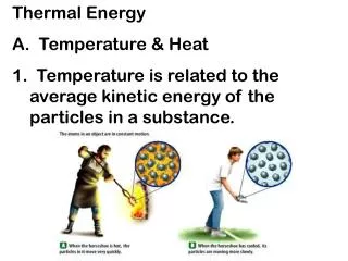
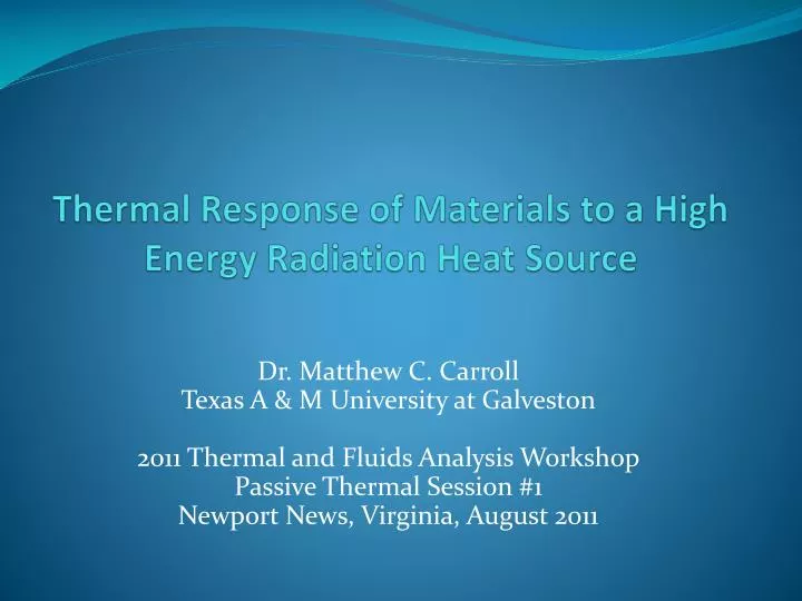
Thermal Response of Materials to a High Energy Radiation Heat Source. Dr. Matthew C. Carroll Texas A & M University at Galveston 2011 Thermal and Fluids Analysis Workshop Passive Thermal Session #1 Newport News, Virginia, August 2011. What are we doing? The Big Picture. Also, many thanks to:

E N D
Thermal Response of Materials to a High Energy Radiation Heat Source Dr. Matthew C. CarrollTexas A & M University at Galveston2011 Thermal and Fluids Analysis WorkshopPassive Thermal Session #1Newport News, Virginia, August 2011
What are we doing?The Big Picture Also, many thanks to: Chris Kostyk and Stephen Miller our Session Chairs.
Main Objectives Formulate a volumetric heat generation term that accurately models the energy deposition in a solid structural material resulting from a high-energy radiation heat source. Develop a solution for the temperature distribution in this material for the cylindrical and spherical geometries resulting from this energy deposition and resulting heat generation.
Solutions depend on ... Geometry • Rectangular (Plane Wall) • Cylindrical • Spherical • Toroidal Heat Generation Modeling • Surface Heating • VEDED (Volumetric Exponentially Decaying Energy Deposition)
Why is multi-group modeling necessary? Taken from W. H. McMaster, et. al., Lawrence Radiation Laboratory, Livermore, California
What use are series solutions? • Since a convergent series can be evaluated to arbitrary precision, series solutions are essentially exact solutions that can be used to benchmark finite difference solutions. • Series solutions are relatively easy to program and can thus be used in the preliminary analysis that traditionally accompanies concept design.
Four Cases • Concave Cylindrical GeometryInside radius faces radiation source. • Convex Cylindrical GeometryOutside radius faces radiation source. • Concave Spherical GeometryInside radius faces radiation source. • Convex Spherical GeometryOutside radius faces radiation source. Derivation is done for concave cylindrical geometry. Other cases are similar.
(1) Partition Radiation Spectrum For a spectrally distributed radiation source, a partitioning of the radiation spectrum should be made into N individual groups, with each group in a certain wavelength interval. For groups i = 1 through J, the mass attenuation coefficient is small enough to necessitate modeling as a volumetric heat generation term, withmi = mass attenuation coefficient for group i Pi = power fraction: fraction of total power in group i For groups J + 1 through N, the attenuation coefficient is large enough that the group can be assumed to cause surface heating.
(2) Develop Governing Equation • General Heat Conduction Equation, Cylindrical Coordinates • Steady State, Constant Thermal Conductivity • Axisymmetric, Neglecting Axial Effects
(3) Formulate Heat Generation Term • Energy flux at point r in the wall due to group i:where q = total radiation flux (W/m2) Pi = power fraction group i r1 = inner radius of wallmi = mass attenuation coefficient group i
Conduct energy balance on arbitrary cylindrical shell of thickness dr to obtain heat generation from group i: • Volumetric heat generation term from all groups: • Key step! Expand exponential into MacLaurin series:
Regroup terms and reverse order of summation to get: • Or in simpler form:
(4) Establish Boundary Value Problem • The boundary value problem with the heat generation term can then be formulated as:
Note the Following • A and the an are as defined before. • At the inner boundary (facing the radiation) r = r1 there is a Neumann condition corresponding to the radiation energy groups with high attenuation coefficients. • At the outer boundary (bordering the coolant) r = r2 there is a Dirichlet condition corresponding to the coolant temperature plus a temperature difference due to convective heat transfer. This depends on the coolant configuration.
(5) Solve Boundary Value Problem • By superposition, the solution T(r) can be considered to be of the form • where T1(r) is the solution of • T2(r) is the solution of
and the φn(r) are solutions of • All three of these differential equations can be easily solved to obtain the following general solution: • Applying boundary conditions to solve for C1 and C2 and rearranging terms, we obtain the final solution for the concave cylindrical case.
Final SolutionsCylindrical Geometry • Final solution for concave case is: • Similarly, final solution for convex case is:
Final SolutionsSpherical Geometry • Final solution for concave case is where s = -1 and final solution for the convex case is where s = 1, wheresr2 < sr < sr1 with r1 the radial coordinate of the surface on the radiation side and r2 the radial coordinate of the surface on the coolant side:
The equations look worsethan they are ... “It must be 10 feet tall,” he said, “And big, and fat, and bad, and red. And it can bite, and kick, and kill, and it will do it, yes it will!” From A Fly Went By, Dr. Suess But seriously, they are not hard to program.
For example: this is the code for the subroutine that calculates temperatures for the convex cylindrical case (in FORTRAN 90). DOUBLE PRECISION FUNCTION TEMP5(R) DIMENSION F(100), U(100) DOUBLE PRECISION F,K,Q,R,R1,R2,T0,U,UEFF DOUBLE PRECISION AN,ARG,FAC,RATIO,RSET,SUM COMMON F,J,K,NLAST,Q,R1,R2,T0,U,UEFF SUM = 0.0 FAC = 1.0 RATIO = R/R1 DO 60 N = 1, NLAST AN = N FAC = FAC * AN ARG = -UEFF*R2 RSET =R2**AN*DLOG(RATIO)+R1**AN/AN-R**AN/AN 60 SUM = SUM+QB*UEFF**AN*DEXP(ARG)*RSET/FAC TEMP4=T0+R2/K*(DLOG(RATIO)*SUM) RETURN END
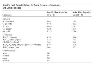
Sample Calculation:Corrugated WallFusion Plasma Chamber • A typical corrugated wall design consists of a 1.0-mm thick corrugated stainless steel panel bonded to a3.0-mm thick stainless steel backing plate. The material used is usually PCA (“Primary Candidate Alloy”), a type 316 stainless steel with about 70%,16 – 18% chromium, 10 – 14% nickel, and small amounts of molybdenum, manganese, silicon, and carbon. • A four-group partition is used for the radiation spectrum. The two low-energy groups are modeled as surface heating. The high-energy groups have P1 = 10% with m1 = 3.552 cm-1 and P2 = 40% with m2 = 43.61 cm-1, respectively.
Total wall power loading is about 77 W/cm2 and distributed over a large range of wavelengths. There is also about 23 W/cm2 cyclotron and charged particle radiation which is low energy and modeled as surface heating. • Coolant in the corrugated wall channels is at about 2000 psig with 280oC and 320oC inlet and outlet temperatures. A 50oC temperature rise across the coolant-wall interface is a good estimate for most conditions so the boundary condition becomesT = 370oC at the outer surface. • Plane wall, concave, and convex solutions are all applicable for this situation.
Results: Temperature ProfilesConcave, Planar, Convex Wall Sections
Conclusions • The series solutions work fine and accurately predict temperatures in materials subjected to high-energy radiation heat sources. • The series solutions are fairly easy to program. It can be somewhat complex to apply the boundary conditions for the various cases. • For the alternating series solutions, additional precision may be needed, as the individual terms get very large before getting small and yielding the final temperature.
Acknowledgements • Work funded by Startup Grant #169310 from TexasA & M Galveston. • NASA, for their strong encouragement for me to continue these investigations in the midst of several other research projects and areas. • Dr. Vijay Panchang, Head, Department of Marine Systems Engineering and Marine Engineering Technology, for collecting and developing a team of researchers; for encouraging and mentoring them; for transforming the department into one optimally balanced between teaching, research, and service.