Download
1 / 27
270 likes | 280 Views
Indexable Ball Endmill. INDEX. 1. LINE-UP. 2. LBE ( LASER BALL). 3. GBE. 4. BRE. Ver. 00 _ TE TEAM 2013. 03. Tool Application. Helical. Copying. Chamfering. Shouldering. Hole boring. Ramping. Grooving. Facing. BRE. G B E. LBE. Line-Up. Ø 63. Ø 50. Ø 40. Ø 30.

E N D
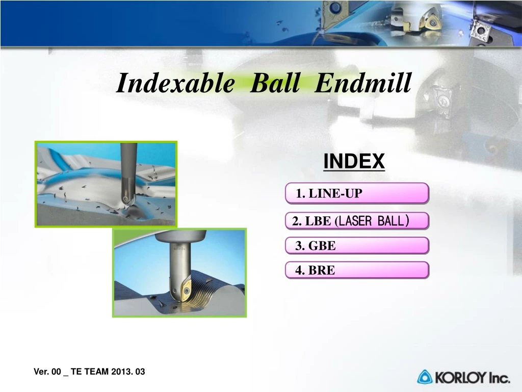
Indexable Ball Endmill INDEX 1. LINE-UP 2. LBE (LASER BALL) 3. GBE 4. BRE Ver. 00 _ TE TEAM 2013. 03
Tool Application Helical Copying Chamfering Shouldering Hole boring Ramping Grooving Facing
BRE G B E LBE Line-Up Ø63 Ø50 Ø40 Ø30 Ø20 Ø10 fz(mm/t) 0.1 0.2 0.3 0.4 0.5
Indexable Ball Endmill MachiningFlow Roughing: BRE Medium, Roughing: GBE Medium, Finishing: GBE Finishing: LBE
LBE Laser BallEndmill • high precision finishing ball endmil
Laser Mill Through coolant hole High precision Screw clamp • Rigid holder • steel • - carbide Features of Laser Mill • High precision finish ball endmill • Simple design of rigid holder • MQL for optimal coolant action for mold machining • Harder grade for long tool life
Laser Mill • Comparison of Indexable Endmill
Laser Mill General type - Steel shank : 25 type - Steel + Carbide brazing shank : 16 type - Steel + Carbide brazing shank : 16 type (Strengthening holder part) Modular type - Steel modular : Head(7 type), Adaptor(29 type) - Carbide : 12 type - Carbide : 12 type (Strengthening holder part)
Radial force Radial force Radial force Feed force Feed force Feed force Laser Mill High feed mechanisms (LFH) • Specially designed cutting edge line enables the good surface roughness • even under the high feed machining 1. Large AA⁰ + Minor cutting edge angle 2. Tangential edge line between minor and major cutting edge 3. Smooth chip evacuation due to recess part ※ According as the approach angle becomes larger, feed force decreases gradually.
Laser Mill • Chip geometry • LFH insert : Corner R programming (mm) (mm/t)
Laser Mill Classification of endmill
Laser Mill • LBE 6 in 1 system R-tolerance Under 0.01 mm LBE * PC210F : PVD (TiAlN) + Super fine grain substrate 6 in 1 system Ball type corner “R” High Feed Chamfer LRH LCF LFH LBH UP UP LBS LR
Example of Customer Test #1LBS LBS300 PC210F 7.5 hrs CY250 6 hrs 5 Holes on machined surface Tool life (Machining time)
Example of Customer Test #3LCF Chamfering Center drilling
GBE General IndexableBallEndmill
GBEGeneral Indexable Ball Endmill Holder Inner Coolant projection Contact surface • Various holder line-ups • (Standard, Long, Long Edge) • Inner Coolant • Tip Seat with projection part • - Stable clamping system against • changing feed direction(curve machining) Long H/D Long Edge H/D StandardH/D
GBEGeneral Indexable Ball Endmill • Superior in High precision and high • depths of cut machining • - Run out(vibration) : Less than 0.02mm • - “R” accuracy: Less than 0.02mm • Various line-ups • - possibility of optimized cutting • -Ф20, 25, 30, 32, 40, 50 • Helical cutting edge • - Minimal cutting resistance • Concave bottom • - Anti-rotation • - Prevention from separation of I/S • Flank support • - Anti-rotation/ Stable clamping Features Main Insert Sub Insert Insert Rdesign for high accuracy side edge for high depths of cut machining Flank support Concave bottom
G B E 3 0 0 – S 32 General Indexable Ball Endmill Cutter Dia φ Type Shank Dia Φ Ф16, Ф20, Ф25, Ф30, Ф32, Ф40, Ф50 S : Standard Shank L : Long shank Standard type Multi Edge type Modular type Projections GBEGeneral Indexable Ball Endmill Holder Code system • Available diameters: Ф16,20,25,30,32,40,50 • Various holder types (Standard, Multi Edge, Modular type etc.) • Inner Coolant System for better chip evacuation • Projection assembled to insert for easy and stable clamping
Z P E T 1 5 0 M - MM Insert shape Clearance angle Tolerance Cross section Nose “R” R8 R10 R12.5 Insert position M-inner S-Outer Chip breaker R16 R20 R25 Concave part Side flat part Internal insert External insert GBEGeneral Indexable Ball Endmill Insert Code system • High precision in high depth ball end milling • - Run-out : within 0.05mm - “R” precision : within 0.05mm • Helical cutting edge for less cutting load • Concave part for preventing vibration, Side flat part for stable clamping • 2 inserts for high quality machining and longer tool life • Newly developed special inserts
GBEGeneral Indexable Ball Endmill Recommended cutting conditions
GBEGeneral Indexable Ball Endmill Wear resistance test 1. Machining length : 1200 mm
GBEGeneral Indexable Ball Endmill Wear resistance test 2. Machining length : 1200 mm
BRE Ball Roughing IndexableEndmill
BRE Insert • Helical cutting edge • - Minimal cutting resistance • Wider Insert • - Increase of cutting • edge strength • Side-end shape • - Increase of • clamping power • Ballpart,Side part • - The application of same I/S • Chip Pocket • Special surface treatment • - Improved external quality Holder • D: Φ20 ~63 • standard/ Long H/D • Long Edge H/D