Download
1 / 83
830 likes | 977 Views
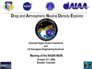
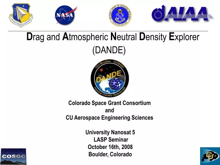
D rag and A tmospheric N eutral D ensity E xplorer (DANDE). Colorado Space Grant Consortium and CU Aerospace Engineering Sciences University Nanosat 5 LASP Seminar October 16th, 2008 Boulder, Colorado. DANDE LASP Seminar. Overview Introduction Science Systems Engineering

E N D
Drag and Atmospheric NeutralDensity Explorer (DANDE) Colorado Space Grant Consortium and CU Aerospace Engineering SciencesUniversity Nanosat 5 LASP SeminarOctober 16th, 2008Boulder, Colorado
DANDE LASP Seminar Overview • Introduction • Science • Systems Engineering • Electronics • Structure, Separation, Thermal • Integration, Testing, Schedule
The University Nanosat Program • University Nanosat – The National Championships of Spacecraft Design • 2 year program in its fifth iteration • 10 out of 30 university proposals selected based on Air Force Relevance • $85k initial seed funding for hardware and student support • In January 2009, one school wins additional $85k, I&T at Kirtland, and flight to Orbit • CU Nanosat Entry • Has involved a core team of graduate students and expanded into 40 graduate and undergraduate students • Many aspects of the ASEN Graduate Projects but organized as independent research and MS research • Has leveraged over $240k from University, Department, DoD, and COSGC Funds I - Introduction
PI’s C. Koehler, S. Palo, J. Forbes Gov. & Academic Support Industry Support STUDENTS Graduate Student Team Subsystem Lead Engineers Undergraduate Student Engineers Collaborations UNP AFSPC/A9A AFOSR AFRL NOAA I - Introduction
Operational Importance of Drag The density of the atmosphere in this region varies greatly (300% to 800%*) due to space weather and not yet understood coupled processes. Relative Orbit of Two Separating Spacecraft 410 km X5 flare7/14/2000 drag induced drift 390 km 370 km decay reboost 350 km ISS drops 10kmin several days 330 km 2000 2001 1999 E. Semones et.al. WRMISS 10 http://www.oma.be/WRMISS/workshops/tenth/pdf/ex02_semones.pdf * Forbes et. Al. “Thermosphere density response to the 20-21 November 2003 solar and geomagnetic storm from CHAMP and GRACE accelerometer data”, Journal of Geophysical Research, Vol. 111, June 2006 I - Introduction
Scientific Importance of Drag CHAllenging Minisatellite Payload Satellite drag measurements suffer from errors caused by • Unknown acceleration contribution from in-track winds • coefficient of drag accuracy Starshine I I - Introduction
: as : DANDE The DANDE Analogy DANDE will measure density, composition, and wind along its orbit I - Introduction
Introduction to DANDE DRAG and ATMOSPHERIC NEUTRAL DENSITY EXPLORER Mission Statement Explore the spatial and temporal variability of the neutral thermosphere at altitudes of 350 - 200 km, and investigate how wind and density variability translate to drag forces on satellites. I - Introduction
Nanosat V Program at CU DANDE will improve atmospheric models and calibrate near real-time models by measuring the following • Deceleration • Atmospheric composition • Horizontal Winds DANDE is spherically shaped to minimize biases resulting from estimation of the drag coefficient I - Introduction
Science Marcin Pilinski 10
How Measurements are Made Identifying all components of the constituents of the drag equation. With a near-spherical shape, an a-priori physical drag coefficient may be calculated and a physical density can be obtained from the measurements A atmosphere ρ - density VW FD V CD tracking WATS sensor accelerometers solution a priori knowledge a priori knowledge a priori knowledge comparison solved II - Science 11
Low frequency bias spin rate ANALOG FILTERING A/D CONVERSION LEAST SQUARES 70 ng Accelerometer Measurement System II - Science
Accelerometer Analysis ACC-2 ACC-4 ACC-1 ACC-6 ACC-3 ω ACC-5 R T ACC-2 FD ACC-1 ACC-3 ω = π/3 [rad/sec] ACC-4 PROCESS & AVERAGE ACC-5 ACC-6 II - Science
82∘ 82∘ 82∘ -82∘ -82∘ -82∘ 0∘ 0∘ 0∘ 0∘ 0∘ 0∘ 82∘ -82∘ 0∘ 0∘ Accelerometer Analysis Latitude [deg] II - Science
Neutral Mass Spectrometer (NMS) ION DISTRIBUTION INCOMING NEUTRAL DISTRIBUTION ELECTRON DISTRIBUTION channel 1 channel 2 ..... channel 7 channel 8 channel 9 channel 10 channel 11 channel 12 INSTRUMENT FOCAL POINT MCP ANODES II - Science 15
Neutral Mass Spectrometer • Neutral particle (blue) enters the collimator. (Ions rejected) • Neutral particle is ionized inside of a field free electron bombardment region • Neutral particle enters the energy selector and undergoes acceleration towards the exit • Outside the selector, the particle is accelerated abruptly by a -3kV potential towards the Micro-Channel Plate (MCP) • The impact on the MCP causes a cascade of electrons to travel towards one of the anodes which measures the impact. Which anode is triggered depends on the angle at which the neutral particle entered the collimator. II - Science 16
NMS Science Data Product Analysis wind angle O wind mag. N2temp. O temp. N2 wind mag. II - Science 17
Density Error – Drag and Wind Data normally distributed zero-mean wind measurements RMS= ±30 m/s II - Science
NMS Status and Future Work • NMS structure built at LASP • First round of testing scheduled for November 17th-21st at NASA, Goddard II - Science
Systems Engineering Mike Grusin 20
Baseline Configuration ESPA Ring DANDE Sphere 18” Lightband Adapter Bracket (LAB) DANDE Overview III - Systems Engineering
Day 2 Day 1 LV SEPARATION AND COMMISSIONING PHASE Wind Composition Acceleration Tracking Tracking Day 9 Day 100 DATA ACQUISITION 1 orbit SCIENCE 1 orbit STANDBY DOWNLINK/UPLINK ~2x in 24 hours ATTITUDE ADJUST ~1 orbit per day RE-ENTRY DYNAMICS ~LAST WEEK OF ORBIT 200 km – 100 km SCIENCE PHASE Mission Timeline • Phase 1: LV Separation and commissioning • Launch Mode - time delay – Safe Mode • Full charge and checkout[18 – 30 hours] • Lightband jettison • Phase 2: Attitude Acquisition • Spin Up [24 h] • Spin-Axis Alignment [120h] • Reserve time [24h] • Phase 3: Science [~90 days] • Science Mode • Standby Mode • Comm. Pass • Attitude Adjust • Repeat III - Systems Engineering 22
FOV360° FOV360° EPS EPS Photovoltaics 30W Photovoltaics 30W CDH CDH SFT SFT ACC ACC Acc Acc I2C bus I2C bus 8 MB NOR FLASH (SFT) 8 MB NOR FLASH (SFT) Linux OS Linux OS Inhibit x4 Inhibit x4 Battery A 12V 4AH Battery A 12V 4AH Battery B 12V 4AH Battery B 12V 4AH ModeManager COM proc ADC proc ACC proc NMS proc ModeManager COM proc ADC proc ACC proc NMS proc Acc Acc Acc Acc Charge Charge 32 MB SRAM 32 MB SRAM Inhibit x4 Inhibit x4 CPU AVR32 120MHz Atmel CPU AVR32 120MHz Atmel Analog Analog RS-232 RS-232 Regulation Regulation Control ATmega128 Control ATmega128 Acc Acc Acc Acc Acc Acc SEP SEP HOP1SpaceDev HOP1SpaceDev Control ATmega128 Atmel Control ATmega128 Atmel 64 MB CF CARD (DATA) 64 MB SD CARD (DATA) LSRM1SpaceDev LSRM1SpaceDev RTC RTC Passive nutation damper THM Coatings, Insulation Release sensors Release sensors Sensors LSRM2 SpaceDev LSRM2 SpaceDev ADC THM Coatings, Insulation Sensors HOP2SpaceDev HOP2SpaceDev X torque rod NMS NMS Control ATmega128 Atmel Control ATmega128 Atmel Data Acquisition Data Acquisition HV sources HV sources COM COM Switched power Switched power Tx Ant FOV+/-80° off nadir Tx Ants Transmitter Symek 70cm (436MHz) 38.4kbps TNC Symek FOV+/-80° off nadir Transmitter Symek 70cm (436MHz) 38.4kbps TNC Symek 38.4kbps modem Control ATmega128 Atmel Y torque rod 38.4kbps modem Amp Symek 7W Pwr Amps Symek 7Wx2 Magnetometer Honeywell HMR2300 9.6kbps modem WATS instrument CSGC / GSFC WATS instrument CoSGC / GSFC 9.6kbps modem Rx Ant Rx Ant Receiver Hamtronics 2m (150MHz) 9.6kbps Receiver SpaceQuest 2m (150MHz) 9.6kbps FOV360° FOV360° Horizon Crossing Indicator A Servo Horizon Crossing Indicator B Servo Critical power Critical power FOV 2° FOV 2° 90° Functional Block Diagram Functional Block Diagram Wiring Harness LV electrical interface Lightband Adapter Bracket assy. Lightband assy. Satellite Sep Plane (SSP) FOV 32° x 1.8° III - Systems Engineering 23 23
Inside of DANDE horizon crossing indicator (x2) battery box (x2) ball & tube nutation dampener (x2) mass trim system (x8) Accelerometers (x6) 3-axis magnetometer patch antenna (x3) EMI box (x3) wind sensor Stiffeners (x4) separation mechanisms (x2) EGSE connector kinematic mounts (x4) lightband adapter bracket III - Systems Engineering
DANDE Attitude • Spin stabilization about orbit normal • 40°/sec (10 rpm) • Only two maneuvers: spin-up and axis alignment • Sensors • Magnetometer for spin-up • Horizon Crossing Indicators for spin axis alignment • Actuators • 2x Torque rods: one along spin axis and one transverse • Passive nutation damper I - Objectives and Requirements 25
Electronics Brandon Gilles 26
Communications Overview LOW POWER RF HIGH POWER RF Ground Station Spacecraft S’GART POWER AMP LOW POWER RF 70cm PATCH ANTENNA AUDIO CDH RS-232 SYMEK TNC31S MODEM 38,400 TX 9,600 RX SYMEK TX SPLITTER (tbd) S’GART POWER AMP 70cm PATCH ANTENNA SPACE-QUEST RX 2m PATCH ANTENNA 70cm YAGI 2m YAGI AUDIO YAESU FT847 SYMEK ICD MOD PC SYMEK TNC3 MODEM 38,400 RX 9,600 TX LOW POWER RF RS-232 HIGH POWER RF IV - Electronics
FIRST RF Corporation Patch Antenna Communications Testing • Partnership with First RF Corporation • Concept: • ¼-wave patch antenna • Spacecraft acts as ground plane • Transmit Antenna Pair • TX: 1 x 3.72 inch • Gain: -3.5dBi • Beamwidth: 240º • Receive Antenna (estimated) • RX: 1” x 13” • Gain: -20dBi • Beamwidth: 240º IV - Electronics 28
Ground Station Communications • Antennas • 70cm: 38-element Yagi • 2m: 22-element Yagi • Transceiver • Yeasu FT-847 • RF Power output variable up to 50W • IF-Amplifier/Demodulator (IFD) Upgrade for bandwidth • TNC • Symek TNC31S • (2) FSK9601 Modems • 1 x 9600 baud • 1 x 38400 baud • Wired for 9600 up and 38400 down IV - Electronics 29
Command & Data Handling Architecture IV - Electronics 30 30
Software Architecture IV - Electronics 31 31
Inhibits Inhibits Photovoltaic arrays 24 watts, 15 volts Battery Charge control DC-DC Converters Solid-State Relays Main Bus, +12V Unregulated output +5V + + Regulated outputs Battery A 12V 4000mAh Battery B 12V 4000mAh Latchingrelays Latchingrelays +/-15V X 3 X 3 _ _ Ground lines to subsystems Single-point Chassis ground X 1 X 1 Power System Overview Miniature PV strings. 15 V for direct-energy transfer IV - Electronics
Structure, Separation, Thermal Andrew Tomchek 33
2D 1D 1D 3D Separation System 3D: A sphere resting inside a cup • Restricts translational motion in the A, B & C directions at one point. 2D: A sphere resting inside a trench • Restricts translational motion in two directions at one point. • When combined with 3D mount, restricts rotational motion in the A & C axis. 1D: A sphere on a flat plane • Restricts translational motion in the C direction • When two are combined with the 3D & 2D mounts, restricts rotational motion in the B axis. Material Selections: • Male: Al 7050-T745 PER AMS 4050 • Female: S15500 Stainless Steel • Male material is softer than female, reducing stiction. • Materials have flight history with kinematic mounts V - Structure, Separation, Thermal
Evolution of DANDE V - Structure, Separation, Thermal
Manufacturing Advised by Tim Flahertyand Mathew Rhodes V - Structure, Separation, Thermal
Structural Analysis and Testing • Y-Direction • -Shows stress through internal X • Vibe test • Demonstrated Structural Integrity • Low natural frequency (89 HZ) • Trade studies to increase stiffness V - Structure, Separation, Thermal
Thermal • Currently working on trade studies to improve hot and cold cases. Advised by Jenny Young V - Structure, Separation, Thermal
Integration, Testing, Schedule Bruce Davis 39
State of the DANDE Program: Hardware HARDWARE & MANUFACTURING Lessons Learned Engineering Design Unit Competition Review Hardware VI - Integration, Testing, Schedule
Integration Planning – Wiring Harness VI - Integration, Testing, Schedule
I&T Planning – Box Integration • Key Box Design Features • All connectors interface to one surface • PCB boards stack removed easily • Wiring harness flexibility with the fabrication of a new interface board PCB Stack connected to lid Interface board routs electrical lines (contains no circuitry) PC-104 connectors, placed adjacent to hex standoffs Standoffs free-fit into box surface, improves rigidity VI - Integration, Testing, Schedule
I&T Planning – Hemispheres • Unique Design Problem, Unique Challenges • Risk to the launch vehicle • Optimization of Assembly Time (1300 cells) • Ease of Integration / De-Integration • Utilizing Existing Facilities • Cleanliness / Quality Control • Protective Ground Support • Life Testing • Solutions • Build a full hemisphere for practice / testing by Oct 31st • Use crimp-pins to allow for ease of removal • Extensive trade study for optimal cell-to-PCB attachment • Backup plan established with traditional methods VI - Integration, Testing, Schedule
I&T – Upcoming Formal Tests • Roughly 600 formal requirements • Verified through subsystem testing on the flight hardware • 20% currently verified • 50% excepted to be verified on hardware by January ‘09 • 30 planned tests throughout the fall semester • Documented with as-run test procedures Sample of Upcoming Tests: ACC707 - Accelerometer Flight Board Acpt Test ADC710 - Torque Rod Functionality Test COM709 - Long Range Antenna Test EPS705 - Power Board Inhibit Functionality Test NMS702 - NMS Calibration Test (at Goddard) STR710 – MGSE Proof Loading Test As-Run Test Procedure Example Test Report Example VI - Integration, Testing, Schedule
Completed Formal Testing TESTING VI - Integration, Testing, Schedule
Integration & Testing Schedule Today Competition Review VI - Integration, Testing, Schedule
Tall Poles • Resolved Risks (selected) • Personnel Turnover DANDE recently doubled in size from other COSGC Projects • Solar Cell Effects on Drag Detailed study shows surfaces can be characterized • Center of Gravity Management Analysis & reserved mass allocated for CG authority • Current Risks (selected) • Solar Cell Attachment Mitigated by testing, practice and alternative fabrication options • Link Budget / Antenna Testing Mitigated by meeting with industry advisors, re-definition of requirements, de-scope options identified. • Orbital Envelope Mitigated by re-definition of requirements allowing for elliptical orbits. Currently matches 32 of 68 previous military launches (with transfer orbit). Drag chute senior design project ’07-’08 trade study. • Thermal Extremes Mitigated by meeting with industry advisors, identifying trade studies, re-definition of orbital requirements, possible addition of heaters. VI - Integration, Testing, Schedule
LASP Contributions to DANDE LASP has contributed to DANDE for the last two years • Advisement to students • Heritage design references (SNOE) • Sample of procedures / operations LASP has recently become a formal supporter • Established cost effective machining opportunities for precision parts • Supplied materials to stock our cleanroom Thank You to those at LASP who have made this possible: • Tim Flaherty • Caroline Himes • Mike McGrath • Norm Perish • Ed Wullschleger • Jenny Young Thank You I - Objectives and Requirements
Questions dande.colorado.edu