Download

1 / 15
150 likes | 158 Views
Post Mortem Collimators and Movable Objects. Michel Jonker Post Mortem Workshop Cern, 16 & 17 January 2007. Outline. Collimation system Purpose of collimation system Overview of moveable elements Controls architecture Post Mortem Data Post Mortem Analysis Local analysis

E N D
Post MortemCollimators and Movable Objects Michel Jonker Post Mortem Workshop Cern, 16 & 17 January 2007
Outline • Collimation system • Purpose of collimation system • Overview of moveable elements • Controls architecture • Post Mortem Data • Post Mortem Analysis • Local analysis • Global analysis (in correlation with other systems)
Purpose of collimation system • Passive Machine protection • Protect against accidental losses of the beam (kicker misfiring, fast magnet trips, …) • Beam Cleaning • Reduce the beam halo below the level where this would cause magnets to quench
Beam Interlock • The collimation system is an active source of the beam interlock: • End switches not compatible with current mode • Jaw position or gap size out of limits • For Machine protection, gap size should be less than an energy dependent value. • For cleaning efficiency (to avoid magnet quenches) the various collimator families should follow a strict setting hierarchy: aprimary < asecondary < aprotection/tertiary < amachine • Temperatures too high
LHC Collimation system • Over 120 collimatorsincluding tertiary, scrapers, absorbers, phase 2, etc • Distributed over 7 points with a large concentration in point 3 and 7 • Jaw positions are correlatedprimary – secondary – tertiary Also during movements they have to stay synchronised
Collimator types • Collimators: • Primary • Secondary • Tertiary • Other moveable objects: • Absorbers • Protection Devices: TCDQ, TCDI, TCLI, TDI • Scrapers • Roman Pots (Atlas & Totem experiments) NB: Vacuum valves, and BI moveable equipment are not covered by collimation control system and this talk.
Collimator Hardware Side view at one end Per collimator: 5 Stepping Motors 5 Resolvers 7 Position sensors LVDT’s 10 Anti Collision & End Switches 5 Temperature sensors 1 Water flow detector 1 Microphone sensors Vacuum tank Movement for spare surface mechanism (1 motor, 2 switches, 1 LVDT) CFC CFC Temperature sensors Microphone Reference Reference Motor Motor Sliding table Gap opening (LVDT) Resolver Resolver Gap position (LVDT) + switches for IN, OUT, ANTI-COLLISION
Control room Data Base Data Base Controls Network Controls Network Central Collimation Application PM Server Actual Machine Parameters Ethernet Ethernet Data Base Machine Timing Critical Settings Surface support building Machine Timing Distribution Synchronisation Underground, low radiation area Fan out Local Ethernet Segment Motor Drive Control Position Readout and Survey Environment Survey PXI PXI PLC Beam Permit LHC tunnel . . . Collimator Supervisory System (one or two per LHC point) Baseline Architecture • Control room software: • Management of settings (LSA) • Preparation for ramp • Assistance in collimator tuning • Based on standard LSA components • Dedicated graphical interface for collimator control and tuning • Collimator Supervisor System (CSS): • Support building, VME / FESA • Fesa Gateway to Control Room Software • Synchronization of movements • Beam Based Alignment primitives • Takes action on position errors (FB) • Receives timing, send sync signals over fiber to low level (Ramp & Beam Based Alignment) • Synchronization and communication (udp) with BLM • Low level control systems • 3 distinct systems • Motor drive (PXI) • Position readout and survey (PXI) • Environment Survey (PLC) BLM system
Modes of operation • The usual stuff: • Setting Up • Injection • Ramp / Squeeze • Recover • Beam Based optimization Position the collimators (640 motors) according to BLM signals Each jaw moved in turn with 10 um steps, 20 Hz during a second. We would like to keep track of this data for later analysis. • Can we use PM system for “non PM data transient recording” ? • Or should we use measurement system • How about the analysis tools, ease of looking up data, etc.
Post Mortem Data Interlock status Machine Data (mode, energy, ramp time, …) Switch status Motor drive status Motor Positions Resolver position Jaw Positions (LVDTs) Command History (including requests and triggers) Position Limits ? Temperature sensors Microphone data BLM Transient data (if in beam based optimisation mode)
Post Mortem Data • Sampling done at about 10 ms intervals. • Retain data for a period of 10 – 60 s (mostly in the low level systems?). • Data transfer triggered by timing event. • Data collection for microphones, temperatures will extend for some seconds after a trigger. • Estimated volume: 200kb per collimator (x 2±1)
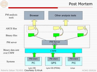
Post Mortem Data • Nothing yet done in terms of structure definition: we are here to learn. • Post Mortem data should be self contained, i.e. alarms and logging is in parallel. or: • Could send all data to the measurement database and let the PM system extract PM data from there.(20 kBytes/second/collimator, if not filtered) • For temperatures we would like to use standard co facilities for PLC based systems.Do they exist, is there a delay of 5 minutes?
Spikes correspond to 2 MJ beam shock impact: Possibility to detect accidental beam impact! Temp Downstream [oC] Temp Upstream [oC] Temp Water Cooling [oC] Post Mortem Analysis Local, specific or pre Analysis Motivation: extract useful information to make this available to the global analysis and to guide the operator. Based on collimator data only. • Did we removed the user beam permit, if so which sub systems. • Could we have been the cause of the trouble:Verification of coherency, misbehaviour of motor positions… • Did we detect any beam impact:beam impact detection (microphones or temperature)… • Did we recover as expected: temperature analysis, etc. Where? i.e. before or after transferring the data.
Post Mortem Analysis Global Analysis, in cooperation with: • Machine data (mode, energy, ramp time). • BLM upstream of collimators. Which collimators got hit when and with how much and can we confirm? • BLM around the ring. (comparison of full BLM system with collimator dependent nominal loss rates, - tricky) • Beam position (comparison of beam position with collimator nominal beam position. • Vacuum system, signs of beam induced out-gassing at the collimators.
Conclusions • No special requirements from collimators • We are a low volume data producer • We are here to learn how to do things • We have ideas on what we should extract and analyse from the primary data, we hope to find here the tools on how to do this. • We would like to understand if PM recording can also be used for transient recording (or if we should use the measurement database).


![[Project Name] Post-Mortem](https://cdn0.slideserve.com/1273592/project-name-post-mortem-dt.jpg)