Download

1 / 60
600 likes | 604 Views
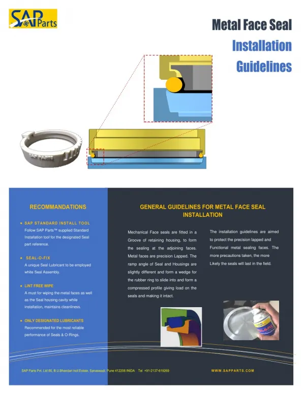
COMPONENT IDENTIFICATION AND INSTALLATION GUIDELINES FLOODBREAK, AUTOGATE. FloodBreak, L.L.C. 2800 Post Oak Blvd., Suite 5850 Houston, Texas 77056. COMPONENT IDENTIFICATION. GATE:. The term “ gate ” refers to the buoyant composite beam itself. Identified here in red. GATE PAN:.

E N D
COMPONENT IDENTIFICATIONAND INSTALLATIONGUIDELINESFLOODBREAK, AUTOGATE FloodBreak, L.L.C. 2800 Post Oak Blvd., Suite 5850 Houston, Texas 77056
GATE: The term “gate” refers to the buoyant composite beam itself. Identified here in red.
GATE PAN: The gate pan is a recessed pan that the gate to and fits into. Identified in green.
INSTALLATION BRACKET: The installation bracket is welded to the gate pan and is used for leveling the gate unit, as well as anchoring the gate unit to the structural footing. Identified in blue.
GATE UNIT: The entire structure, including the gate, gate pan, installation bracket, and wiper walls (not shown here).
INSTALLATIONPLEASE NOTE THAT THE PHOTOS USED IN THIS PRESENTATION MAY REFLECT VARYING SITE CONDITIONS AND ARE INTENDED FOR ILLUSTRATION PURPOSES ONLY
Installation Kit 5/8” AND 9/16” MASONRY BITS PAINT, FILLER PUTTY AND HARDENER GATE ANCHOR BOLTS WASHERS AND NUTS LEVELING BOLTS VINYLESTER CAPSULES STAINLESS SHACKLES AND LIFTING CABLE WIPER WALL ANCHOR BOLTS GRATING LIFTING HANDLES
STEP 1 Identify the size of the of the rough opening required to accommodate placement of the gate unit. EXAMPLE: Proposed gate size 3‘X 25’ The additions to the gate dimension are constant regardless of the gate size. For a 3’ gate the equation to identify the rough opening (r.o.) would read as follows. 3’ (gate) + 1’-3” (gate pan) + 1’ (installation bracket) + 2’ (construction tolerance) = 7’-3”r.o. EXAMPLE: Proposed gate size 5’-6” X 25’ For a 3’-6” gate the equation to identify the rough opening (r.o.) would read as follows. 5’-6”(gate) + 1’-3” (gate pan) + 1”(installation bracket) + 2’ (construction tolerance) = 9’-9”r.o. THE ROUGH OPENING DEPTH IS THE “UNIT DEPTH” + 3” • STANDARD = 12” • ROADWAY = 16”
STEP 2 Make two parallel saw cuts the correct distance apart as is determined by the rough opening dimension
STEP 3 Break out, and haul off site the existing concrete.
STEP 4 Excavate, and haul off site, the existing base to the required depth to accommodate the structural footing
STRUCTURAL FOOTING The structural footing is a concrete footing placed 16” below finished grade to a depth determined by others. Varying geotechnical conditions and temperatures typically determine the required depth. Consultation with an engineer or local contractor is highly recommended. Load specifications are to be equal to or greater than the existing or proposed driveway design.
STEP 5 Place the 4” drain to storm sewer or exit point, centered both directions in the rough opening, leaving the “stub up “ high (above finished grade) to be cut off at the time of placing the gate unit.
STEP 6 Place re-bar and concrete for structural footing (first lift)
STEP 7 Remove all crating material from the gate unit. Including the wiper wall support angles and square tubing shims.
STEP 8 Using a spreader-bar of adequate length to make a two point lift, lift the gate unit from the trailer and swing it into position over the rough opening.
STEP 9 Leaving the gate unit suspended over the rough opening, screw the leveling bolts (provided) into the installation bracket approximately 1 ½” – 2”. When the gate unit is placed it should be very close to finished grade. Leveling Bolt
STEP 10 Cut off the 4” drain to allow the leveling bolts to sit firmly on the structural footing when the gate is placed. NOTE: Using a site level, make a mark on the 4” pipe at finished grade. Measure down from finished grade 4 ½” and cut off the pipe. This will leave some pipe in the pan to be finished later.
STEP 11 Place the gate unit in the rough opening making sure to keep the gate unit square with the existing structure before anchoring
STEP 12 Level the gate unit to match existing grade.NOTE: Using a site level, shoot several points on the existing concrete (both sides) to determine an “average” finished grade. Placing the mast on the finish angles of the gate unit, take shot at every leveling bolt location and use the leveling bolts to bring the gate unit to “average” finished grade.
STEP 13Anchor the gate unit to the structural footing. Using a rotor hammer and a 9/16” masonry bit (provided) drill a minimum of 6” into the structural footing by placing the into the anchor holes located adjacent to the leveling bolts. Once the holes are all drilled, it is vey important to remove all dust from the holes by using a vacuum or compressed air. After the holes are thoroughly cleaned you can then drop the epoxy capsules (provided) into the holes. Place the ½” stainless all-thread bolts into the holes and strike with a hammer to ensure that the capsule is broken and the epoxy is released. Allow the anchor bolts to “set” for about an hour to an hour and half, depending on the ambient temperature, or until secure. Once set you can then bolt down the unit. Using a grinder with a cut-off wheel, remove the excess all-thread protruding above finished grade. Open the gate and put the prop-rods (located in the pan) into place making sure to use the safety pin to prevent the gate from falling. Repeat the anchoring process using the holes located on the retention arm brackets. The all-thread bolts used on the inside of the pan must be ground off flush with the top of the nuts to ensure proper closing of the gate. Return the gate to the closed position.
STEP 14 Anchor the wiper walls to the existing structure. Using a rotor hammer and ½” masonry bit (provided) drill into the existing structure far enough to receive the wedge anchors and bolts (provided) by placing the bit into the pre-drilled holes in the wiper walls. Place the wedge anchors and bolts into the holes and tighten while ensuring the wiper walls are plumb and square to the gate surface. Sand the area around the bolt heads to remove the paint. Apply the two part putty (provided) to the sanded areas using the applicator provided. Allow the putty to harden and sand smooth.
STEP 15 Protect the entire gate unit using duct tape and plastic to keep any concrete from getting on the gate unit.
STEP 16 Place the second lift of concrete to finished grade.NOTE: It is critical to pour the concrete from the front side or “wet side” and vibrate to the back to avoid any air pockets.