Download
1 / 6
60 likes | 200 Views
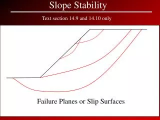
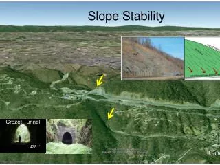
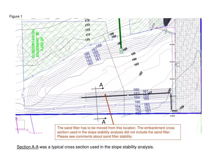
Figure 1. A. A. The sand filter has to be moved from this location. The embankment cross section used in the slope stability analysis did not include the sand filter. Please see comments about sand filter stability.

E N D
Figure 1 A A The sand filter has to be moved from this location. The embankment cross section used in the slope stability analysis did not include the sand filter. Please see comments about sand filter stability. Section A-A was a typical cross section used in the slope stability analysis.
Figure 2 6 layers of woven geotextiles Details 2 Soil-vegetated protection cover on both sides of the slope and the crest 1 Compacted A-2-6 Soil layers 2- 3 ft Overlap Woven Geotextile layers (Tensile Strength (at ultimate) ASTM D 4595 < 250 lbs/ft 27 ft
C L 1 C L 1 Figure 3 6 layers of woven geotextile 2 to 3 ft Overlap. 1 ft 6 in lift of SC or A-2-6 compacted soil (95%) Standard Proctor ASTM D698 1 ft 1 ft 1 ft 1 ft 1 ft 1 ft 9 ft 2 to 3 ft Overlap. If the full length can be Covered, there is no Need for overlap Embankment Key
Figure 4 Embankment - Retaining Wall Section Retaining Wall Extend the mat by 6 in to partly cover the wall 2 ft Embankment 6 in Overlap Slope of at least 2% to 3% Slope of at least 2% to 3% • Use Mirafi HS1715 or equivalent erosion protection layer on the top of the • upstream, crest and downstream of the embankment • 11 Gauge, 6” (15.24 cm) x 1” x 6” (15.24 cm) metal staples to fasten the mat • Use 6 in overlap • Fasten every 3’ to 5’. On the overlap staple every 1’ • Seed and fertilizer may be spread before or after mat installation
Wall 4 to 6 in slanted soil Soil Lift
Embankment Construction and Selection of Materials: • Fill slopes shall not be steeper than two-horizontal to one-vertical (2h:1v). • The ground surface shall be prepared to receive fill by removing vegetation, non-complying fill, topsoil, and other unsuitable materials. • Pond embankments shall be constructed on suitable native consolidated soil (or adequately compacted and stable fill soils) • The embankment soils shall have the following minimum/maximum soil characteristics per the United States Department of Agriculture’s Textural Triangle: a minimum of 30% clay, a maximum of 60% sand, a maximum of 60% silt, with nominal gravel and cobble content. Or use A-2-6 soil according to AASHTO soil classification system. • The embankment soil shall be free of loose surface soil materials, roots and other organic debris. • No rock or similar irreducible material with a maximum dimension greater than 6 inches (6") shall be buried or placed in fills. • The Geotechnical Engineer shall properly devises a method of placement and continuously inspects its placement and approves the fill stability • All embankment layers shall be adequately compacted in 6” lifts to achieve 95% of maximum dry density (use pneumatic rubber-tired). Field compaction must be inspected to insure the achievement of the 95%. Inspection should be done every 45’ to 50’. • Use hand vibratory compactor to compact the soil lifts for a distance close to the retaining wall (0 to 6 ft from the wall) • See section of the embankment-retaining wall section for more details. The wall needs to be design accordingly. • The embankment shall be placed approximately 10% higher than required by the design to account for the long term settlement of the fill material • Exposed earth on the side slopes and bottom should be seeded with the appropriate seed mixture as soon as is practicable.