Download

1 / 12
120 likes | 241 Views
Selecting & Defining Command and Control Systems for Mine Ventilation. Presented By: Sancar James Fredsti. Abstract:. Harsh Environment for Equipment Communication between components is critical. Robustness of system configuration is essential to successful design approach.

E N D
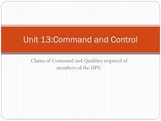
Selecting & DefiningCommand and Control Systems for Mine Ventilation Presented By:Sancar James Fredsti
Abstract: • Harsh Environment for Equipment • Communication between components is critical. • Robustness of system configuration is essential to successful design approach. • As systems age, often the configuration becomes unmanageable as equipment becomes obsolete. • Flexible design, ease of maintenance and expandability are paramount considerations.
Introduction: • Huge offering of equipment in market place overwhelms system designer with choices. • Incompatible communications methods and protocols leads to cumbersome system configuration. • Often systems created from ‘available’ components will become dysfunctional over time because of software and hardware upgrades. • Implemented on University of Nevada, Reno ventilation on demand simulator system. Which desired real time data collection, simplified operation and easily modified structure and design.
Pre Modification System • 20 Manual pressure sensor points. • 4 Anemometer sample points • National Inst. Analog & Digital I/O Interfaces • Regulator control through simulated stepper motor control • Fan control through analog driver, fed from remote analog speed transducer. • Centralized instrument and control points
System Description & Design Approach • Old system design approach inadequate • Need to simplify system Old System Operations Approach
Design Methodologies Available • Design by use of off the shelf components • Design by adapting system to fit network • Custom design from the ground up
Design By Using Off The Shelf Components • Selection of components with compatible specifications is difficult. • Interfacing different manufacturers equipment is arduous and consumes system software development resources. • Communications often uses multiple protocols and layers, • Lack of definitive data and control topologies common across many manufacturers makes getting system pieces to play nicely together difficult. • Comfortable for system designer to use familiar equipment but usually results in a system that has adaptors, interfaces and translators.
Design System By Adapting To Specific Network • Selection of components with compatible communications limits the availability of hardware. No one offers everything. • Critical to select most useful communications protocol for the application and physical topology. • Keep the hardware and protocol layers similar. Mixing different protocols on the same physical layer leads to errors, failures and potential hazards. • If communications protocols require translation keep this equipment simple and close to the equipment terminus. • Be willing to break network up into manageable sections • Separate and define long haul and short haul as independent sections, this may require a mixture of hardware layer equipment.
Design System From Ground Up • More difficult to accomplish, requires hardware and software development team effort. • Ability to define hardware and interfaces specifically for the application at hand, helps eliminate forcing of hardware to work by software modification and adaptation. • Large selection of networkable controllers, processors and interface equipment. • Ability to define custom networking and interfacing of incompatible equipment. • Ability to design distributed and localized processing of collected data making system efficient and keeping network traffic to a minimum. • Easily accommodate long haul and short haul networking with custom interfaces. • Custom hardware design and building costs can be substantially less than cumbersome software development alone.
Custom Designed UNR System • Simplified system operation while expanding capabilities • Replaced manual pressure sensor system with custom designed networked 20 node dual sensor system • Replaced Interface and control cabinets with networked drivers Final Custom Network and Hardware Design
Applying Design and Selection Philosophies Previous single approaches may yield disappointing results, but a mixture of design philosophies usually results in a successful final product. • Define all parameters required. • Discard approaches that require too much work • Don’t be afraid of designing new hardware • Distribute intelligence throughout the system • Communications is paramount • Use a Top Down approach, define what to do before defineng how to do it. • Keep maintenance and serviceability in mind
Custom UNR Control System Custom designed instrument module. Note: all power, data communications and control signaling is accomplished through a single 4 conductor wire interface. This bus is shared by all modules on the network. Picture shows instrument cluster. 20 Pressure Sensors, 3 Variable Speed Fans, 4 Regulators, 4 Anemometers, 5 CO2 Sensors 4 CO2 Injection points and an Outside Barometric Pressure and Dew Point instrument. Note: all power, data communications and control signaling is accomplished through a single 4 conductor wire interface. This bus is shared by all modules on the network. Cluster of modules on data network.